
Abstract
The paper contains a review of recent advancements in rotating machines with bulk high-temperature superconductors (HTS). The high critical current density of bulk HTS enables us to design rotating machines with a compact configuration in a practical scheme. The development of an axial-gap-type trapped flux synchronous rotating machine together with the systematic research works at the Tokyo University of Marine Science and Technology since 2001 are briefly introduced. Developments in bulk HTS rotating machines in other research groups are also summarized. The key issues of bulk HTS machines, including material progress of bulk HTS, in situ magnetization, and cooling together with AC loss at low-temperature operation are discussed.
Export citation and abstract BibTeX RIS
1. Introduction
Bulk high-temperature superconductors (HTS) exhibit a high critical current density Jc and have a strong diamagnetic response. They present a great capability to trap magnetic flux density (17 T at 29 K being the present record [1]), more than an order of magnitude higher than Nd–Fe–B magnets which are the strongest permanent magnets to date. This fact makes bulk HTS promising for applications like magnetic levitation, brushless rotating machines, magnetic bearings and flywheels, superconducting mixers, magnetic drug delivery systems, magnetic resonance microscopes and so on [2].
Rotating machines with HTS are attracting considerable interest. Thanks to the higher magnetic flux that HTS material can supply, HTS rotating machines provide an increased power/torque density compared with conventional ones, resulting in a smaller size and a lighter weight. Since the Joule heat generated in the copper coils and the hysteretic and eddy currents losses of the ferromagnetic core in conventional machines are practically eliminated by employing HTS material, the efficiency of HTS rotating machines can be largely increased compared with conventional ones, even taking into account the cooling power of HTS elements [3]. It is worth noting that except for the superconductor part, the targeted high power density requires additional work on the conventional non-superconductor part, i.e. armature or stator, for example by better air cooling, cooled wires with a suitable choice of refrigerant as well as LN2/GM machine cooling for HTS. Other advantages of HTS rotating machines are as follows [4]:
- low synchronous reactance and small load angle, large overload capacity;
- high transient stability and grid stability;
- low noise;
- low harmonic content;
- superior negative sequence capability.
Attracted by these unparalleled benefits, many programs have been launched to develop HTS rotating machines, and machines using the excitation of the HTS tape windings already reach up to several tens of MWs. American Superconductors (AMSC), partnered by Northrop Grumman, has developed a 36.5 MW HTS ship propulsion motor for the US Navy. Meanwhile, Siemens assembled and tested a 4 MW machine designed for a marine vessel [3]. In Asia, a 1 MW HTS motor has been developed by Kawasaki Heavy Industries in Japan [5] and also Doosan Heavy Industries in Korea [6]. Programmes of HTS generators are also on their way; for example, the General Electric 100 MVA superconducting generator and superconducting wind generators up to 10 MVA.
Compared with HTS windings, bulk HTS traps an even higher magnetic flux, leading to higher power densities. To demonstrate this more intuitively, photos of a HTS winding and a bulk HTS generating the same value of magnetic field are shown in figure 1. This means that by using the bulk HTS, the mass of the rotating machine can be further reduced. In addition, compared with HTS wires, bulk HTS require no cladding and are much more stable. Until now, a lot of design concepts and prototype machines of bulk HTS rotating machines have been proposed and manufactured by research groups all over the world. In this paper, we give an overview of the progress in rotating machine systems using bulk HTS.
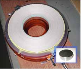
Figure 1. A double-pancake-coil of Bi-2223 HTS wire of diameter 160 mm, able to generate a magnetic field of 1.5 T at 30 K, compared to a Gd–Ba–Cu–O single grain of diameter 30 mm, able to trap the same value of 1.5 T of magnetic flux density at liquid nitrogen temperature.
Download figure:
Standard image1.1. Development and batch production of bulk HTS
RE–Ba–Cu–O (RE denotes rare earth elements) material has a short coherence length and a large anisotropy; thus any high-angle grain boundary will act as a weak link and seriously reduce the critical current density [7, 8]. For engineering applications, high textured single grains/domains are required. During the past 20 years, researchers have achieved significant improvements in the texture growth of bulk RE–Ba–Cu–O. Large-size, high performance RE–Ba–Cu–O single grains are now commercially available.
The trapped magnetic flux density (Btrap) due to flux pinning or induced supercurrents flowing persistently in a RE–Ba–Cu–O grain can be expressed as
where A is a geometrical constant, μ0 is the permeability of a vacuum and r is the radius of the grain. Thus, there are two approaches to enhance the trapped flux of the grain. One is to enhance the critical current density and the other is to increase the size.
It is well known that LRE–Ba–Cu–O (LRE denoting a light rare earth like Nd, Eu, Gd or Sm) exhibits superior flux pinning properties because of the nanometre-scale solid solution clusters originated from the LRE–Ba substitution [9–11]. This kind of solid solution cluster will contribute to a strong δTc pinning and enhance the Jc in intermediate and high magnetic fields. It is one of the reasons that we chose Gd–Ba–Cu–O bulks in our rotating machine. Refinements of RE211 size and distribution and the addition of artificial pinning centres are effective to enhance the Jc and irreversibility field of RE–Ba–Cu–O bulks [12–14]. Various kinds of oxides and RE2Ba4MCuO11 (RE2411 particles, M = Zr, U, Mo, W, Ta, Hf, Nb) are introduced into the RE–Ba–Cu–O matrix as second phase particles to enhance the flux pinning [15–18]. Up to now, the record of Jc reaches 640 and 400 kA cm−2 at 77 K in self-field and 2 T, respectively. This record was achieved in the (Nd,Eu,Gd)–Ba–Cu–O bulk by combining the benefits of dense regular arrays of RE-rich RE123 solid solution, small initial size (70 nm) of Gd211 particles and the formation of extremely small (<10 nm) Nb (or Mo,Ti)-based nanoparticles [19]. Systematic research into the doping effect has been also carried out in our laboratory. Jc of 100, 68 and 80 kA cm−2 were obtained at 77 K in self-field by doping with ZrO2, ZnO and SnO2 particles, respectively [20–22]. Recently, we have reported the doping effect of amorphous magnetic alloy particles Fe0.687B0.121Si0.138Nb0.033Cr0.011Cu0.010 (abbreviated as MP) [23, 24]. The Jc is enhanced in both self- and intermediate fields and shows a good homogeneity in the whole bulk. The trapped flux density and integrated magnetic flux of a 46 mm diameter Gd–Ba–Cu–O grain with 0.4 mol% added MP were increased by 25% and 17%, respectively (figure 2). Furthermore, by employing the MP doped Gd–Ba–Cu–O grains in a rotating machine, the AC losses were reduced, as will be described later.
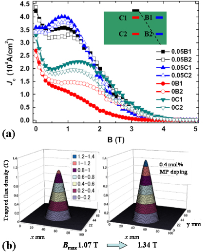
Figure 2. (a) The Jc–B curves of specimens cut from different positions of MP doped and un-doped bulk samples [23]. (b) Trapped magnetic flux density profiles of 46 mm diameter MP doped and un-doped bulks measured after field cooling [92].
Download figure:
Standard imageCurrently, the typical size of RE–Ba–Cu–O grains is 30–60 mm in diameter, suggesting Btrap of 0.8–3 T at liquid nitrogen temperature [25]. As the Btrap is proportional to grain size, grain enlargement is important for enhancing the bulk performance. But the limitation of the growth window and problems such as the presence of growth with inhomogeneity and chemical contamination from the substrate materials make this quite difficult. Despite this, large grains with diameters over 100 mm have been achieved by many research institutes [26]. Figure 3 shows a Gd–Ba–Cu–O single grain of 140 mm diameter fabricated by Nippon Steel Corporation. On the other hand, research has shown that joining RE–Ba–Cu–O grains by using another RE–Ba–Cu–O filler material or direct contact with pressure [27, 28] and the developments of multi-seed process [29] provide other ways to enlarge the size of the bulk HTS.

Figure 3. Top view of a 140 mm diameter Gd–Ba–Cu–O single grain with a stainless steel ring (Nippon Steel Corporation).
Download figure:
Standard imageThe flux-trapping capability of bulk HTS increases significantly with decreasing temperature. RE–Ba–Cu–O grains show a potential trapped flux density greater than 10 T around 30 K [1, 30]. At low temperatures, the trapped flux density is not limited by the flux pinning property but by the mechanical strength of the grain. Addition of Ag during growth is well known to improve mechanical properties [31], and reinforcing the grain using a stainless steel ring has also proved to be effective (figure 3).
Batch processing of melt-textured Y–Ba–Cu–O was realized several years ago [32]. Recently, thanks to the development of cold-seeding technology by using Mg doped Nd–Ba–Cu–O [33, 34] or Nd–Ba–Cu–O thin films [35] as cold seeds, batch processing of high performance Gd–Ba–Cu–O HTS has also been realized. Fabrication of more than 600 kg of HTS bulk material per year has been reported by the Adelwitz Technologiezentrum GmbH (ATZ) [29]. Batch processing of bulk HTS largely reduced the production cost and further opened the gate to large-scale applications.
2. Design concepts and prototype manufacture of bulk HTS rotating machines
2.1. Trapped flux synchronous rotating machines
2.1.1. Axial-gap-type machines.
We initiated the design and manufacture of a series of prototypes with Gd–Ba–Cu–O bulks in 2001; these machines are synchronous ones [36, 37]. They were designed for a propulsion motor, requiring a high torque associated with a low speed ranging from 80 to 720 rpm. The axial-gap-type design we adopted allows the minimization of the machine dimensions and a lateral cryogen flow for efficient cooling of the bulk field poles (figure 4).
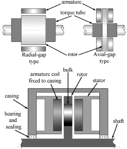
Figure 4. Schematic diagrams of both radial-gap and axial-gap types of rotor structure for comparison [36].
Download figure:
Standard imageThe rotor plate of the HTS rotating machine comprises eight Gd–Ba–Cu–O field-pole magnets, 60 mm in diameter. Twelve (six pairs) vortex-type copper windings work as the stator. The Gd–Ba–Cu–O bulks are magnetized in situ with a pulsed field magnetization (PFM) technique. Some of the vortex-type armature copper coils also play the role of magnetization coils, generating a pulsed magnetic field larger than 10 T by applying a 3 kA current within 6.8 ms. As a result, a trapped magnetic field with a maximum flux density larger than 1 T and a conical shape distribution is established in the Gd–Ba–Cu–O bulks (figure 5). After connecting the armature coils to a three-phase power source via an inverter, the magnetized bulk HTS are brought into a rotating magnetic field, so that the machine functions as a synchronous motor in accordance with Fleming's left-hand rule between the magnetized superconductors and the armature coils. Vice versa, by mechanically rotating the rotor plate, the machine functions as a generator.
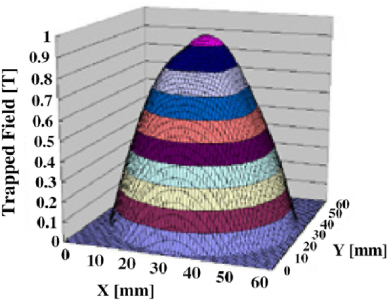
Figure 5. Trapped flux density distribution of a Gd–Ba–Cu–O bulk measured outside the rotating machine. The bulk was magnetized by a pulsed magnetic field of 5.8 T at liquid nitrogen temperature.
Download figure:
Standard imageBoth the schematic illustration and the photograph of the rotating machine are shown in figure 6. Cooling of the field-pole magnets was realized with a closed-cycle thermosyphon system. By using a neon thermosyphon, the bulk HTS poles on the rotor are cooled down to below 40 K [38, 39]. A cryo-rotary joint (cryo-RJ) was designed and installed into the system to introduce the cryogen from the static condenser to the evaporator, implanted in the rotating rotor plate. The cryo-RJ has recently been improved in terms of light weight, small size and reduced heat loss [40]. Figure 7 shows the photograph of the developed cryo-RJ. Commercial magnetic-fluid sealing (MFS) units are employed to prevent a leakage of the cryogen. The testing results were as follows: the average load torque was 0.044 N m, which is negligible compared with the output of any sub-MW class HTS rotating machine; the heat invasion was less than 6.4 W at 700 rpm; no leakage of the cryogen was observed.
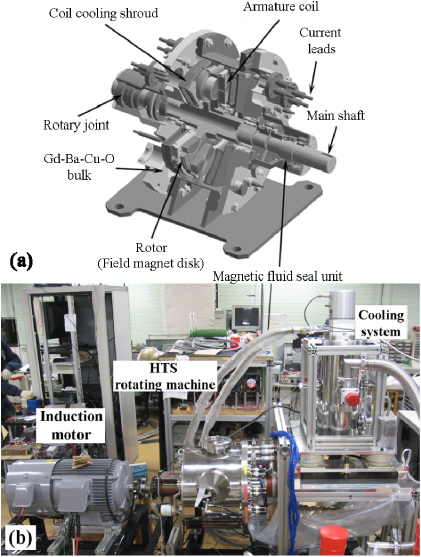
Figure 6. (a) Schematic illustration of a single rotor synchronous HTS motor. (b) A picture of the rotating machine tested as a generator and the neon-thermosyphon cooling system.
Download figure:
Standard image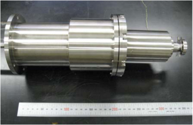
Figure 7. Photograph of the developed cryo-rotary joint.
Download figure:
Standard imageAs shown in figure 4, the bulk field poles are cooled down by conduction cooling through the copper which links the evaporator and bulk HTS. The present design has shortened the air gap between the bulk HTS field poles and armature coils (by 1 mm in the present design) by removing the heat effectively from the bulk. Since the thermal conductivity of bulk HTS in the a–b plane is about three times higher than that along the c-axis, we can afford a sufficient cooling efficiency while saving volume and weight. It is worth mentioning that a coil cooling shroud, as shown in figure 6(a), was designed to allow the flow of liquid nitrogen to refrigerate the armature coils, which are the magnetizing coils during operation and magnetization.
For the design of the torque tube we used G-10, a glass fibre reinforced plastic. Since the convection heat transfer in the vacuum-insulated machine is negligible and the radiation heat transfer is restrained to less than 5 W with a polished copper radiation shield, most of the heat invasion may originate from heat conduction along the main rotor shaft. Thanks to the low thermal conductivity of G-10, possible heat transfer along the main shaft is restrained to be less than 20 W. Considering the mechanical strength of G-10 material, the transmission torque was designed to be 385 N m (29 kW at 720 rpm).
As shown in figure 8 a twinned rotor motor was also fabricated and tested and the output is largely enhanced by piling up the rotor plates. The characteristics of the single and twin rotor motors are listed in table 1 [36].

Figure 8. Rotating propeller operation for single (left) and twin (right) rotor-type bulk HTS motors.
Download figure:
Standard imageTable 1. The characteristics of motors.
| Single rotor type | Twin rotor type | |
|---|---|---|
| Maximum rotation speed (rpm) | 850 | 760 |
| Torque (N m) | 132.7 | 212.3 |
| Average trapped field (T), 77 K | 0.56 | 0.35 |
| Maximum trapped field (T), 77 K | 1.0 | 0.7 |
| Motor output (kW) | 10 | 16 |
The design and fabrication of an axial-gap-type HTS rotating machine was also carried out by Itoh et al in the early 1990s [41, 42]. One of the key points was that they brought the PFM concept into a rotating machine and realized in situ magnetization. The difference was that they used solenoid coils for PFM. The coils were wound around the Y–Ba–Cu–O bulks to form the stator poles. Therefore, an additional disc-shaped armature was required to work as a rotor. Once the armature with radial-commutated current flow was placed between two HTS magnetic poles, the rotor would be driven by the Lorentz force and work as a DC machine.
2.1.2. Radial-gap type.
Considerable efforts to design and develop a wholly superconducting synchronous motor have been made by Coombs et al at Cambridge University. In 2006, a conceptual design of a radial-type machine consisting of both HTS rotating field windings and armature windings was proposed [43]. Soon afterwards, the design and construction of a HTS permanent magnet machine using bulk HTS instead of the rotor's HTS windings was reported [44]. Figure 9 shows a photograph of the prototype [45]. The stator consists of six air-core HTS armature windings, and the rotor is made of 75 (15 columns, five pieces per column) bulk HTS pieces of diameter 30 mm. The bulks are magnetized by copper coils in the upper part of the rig using PFM every 90° and four magnetic poles are established in the rotor. After PFM, the rotor is moved down into the alternating magnetic field. At the moment the system is cooled by immersion in liquid nitrogen. The maximum value of trapped field was reported to be 0.375 T and was obtained after 19 pulses [46]. According to this value, the maximum torque and output power were calculated to be 49.5 N m and 7.8 kW, respectively. It is worth mentioning that the torque ripple problem caused by the irregular distribution of the flux linkage in the air gap has been considered. An iterative learning control algorithm was developed to solve this problem [47].

Figure 9. Prototype of a wholly superconducting synchronous motor developed at Cambridge University [45].
Download figure:
Standard imagePhilippe J. Masson et al (FSU Center for Advanced Power Systems; part of the NASA-DoD URETI program) have described the feasibility of superconducting rotating machines for airborne applications, an attractive and fascinating domain [48]. It seems that superconducting machines offer the only hope of ever achieving electrical aeropropulsion which demands ultra-compact generators and motors. General Electric has demonstrated a very robust homopolar inductor alternator presenting an impressive 7 kW kg−1 of power density at high rotating speed. Unconventional superconducting motors using both Bi-2223 pancake coils and Y–Ba–Cu–O bulks have also been designed and developed at the FSU Center for Advanced Power Systems (figure 10) [49, 50]. A two-step cooling procedure is used in order to first allow the coils to generate the field; with the radial component of the magnetic field, the bulk HTS will be magnetized by field-cooling magnetization (FCM). This kind of motor is easy to scale up by just increasing the length or radius [51]. When scaled up to 1.5 MW, this machine exhibits a potential power density of about 6.6 kW kg−1 (table 2). Another interesting configuration is an axial-flux-distribution-type motor (figure 11) [52]. Bulk HTS is magnetized by field cooling in the magnetic field generated by a superconducting coil located outside the machine. A 450 kW machine based on this configuration was designed, which shows very promising results such as a power density of 7 kW kg−1 and 6 T trapped in the Y–Ba–Cu–O bulks.

Figure 10. Overall view, configuration of the trapped flux machine and calculated flux distribution in the machine developed at the FSU Center and the calculated flux distribution [50].
Download figure:
Standard image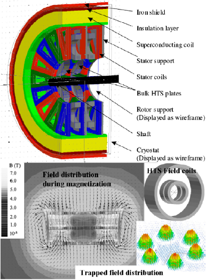
Figure 11. Configuration of an axial flux motor also developed at the FSU Center and its calculated flux distribution during and after FC magnetization [52].
Download figure:
Standard imageTable 2. Motor design parameters [50].
| Radial type | Axial type | |
|---|---|---|
| Total length | 760 mm | 180 mm |
| External diameter | 220 mm | 160 mm |
| Number of poles | 8 | 6 |
| No-load average flux density | 1.8 T | 3 T |
| Electric loading | 80 kA m−1 | 100 kA m−1 |
| EM torque | 4700 N m | 1060 N m |
| Rotation speed | 3000 rpm | 3000 rpm |
| Output power | 1.5 MW | 450 kW |
| Total mass (including conduction cooling apparatus) | 227 kg | 60 kg |
| Power density | 6.6 kW kg−1 | 7.4 kW kg−1 |
| Volume | 0.03 m3 | – |
| Operating temperature | 25 K | 20 K |
A novel configuration has also been designed by Hull and colleagues at Boeing Research & Technology. A schematic illustration of a four-pole rotating machine is shown in figure 12 [53]. The stator core, rotor core, and rotor cap are composed of dysprosium (Dy), formed as thin laminations of a powdered composite to minimize eddy current losses. Once the current in the stator coil is ramped up, the magnetic flux will be concentrated by the stator core and vertically penetrate into the bulk HTS (above Tc). The bulk HTS is then cooled down to trap the magnetic flux (field-cooling method). A key feature of this design is the use of Dy which is ferromagnetic below 80 K and has a much higher magnetic saturation than conventional Fe, which breaks the limitation of the trapped field magnitude of bulk HTS. According to the calculation, a magnetic field as great as 4.6 T is achievable in the air gap by applying a 480 A mm−2 current density in the stator coils; in this case, the HTS excitation coils are necessary. However, as mentioned by the designers, the hysteresis losses caused by the Dy core should be carefully considered.
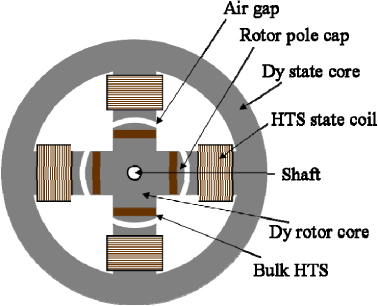
Figure 12. Schematic diagram of the configuration of the rotating system developed at Boeing Research & Technology [53].
Download figure:
Standard imageWeinstein and colleagues from Houston University began the design of bulk superconducting machines in the early 1990s [54]. Recently, a radial flux HTS machine was built and tested at TECO-Westinghouse Motor Company [55]. Hexagonal Y–Ba–Cu–O bulks are closely tile-arranged and magnetized by the stator windings. Both field-cooling and zero-field-cooling magnetizations have been tested to activate the bulk HTS and the magnetization effects have been compared by operating the machine as a generator. The heat generation from the stator windings seems to be a serious problem, especially in the case of field cooling, for which a longer cooling period is required. Thus, it becomes obvious that for the field-cooling method, the use of HTS excitation coils is an essential requirement.
The Central Japan Railway (JR) Company has invested a great deal of effort in the R&D of superconductors. A prototype of a radial gap, outer rotor-type synchronous motor was designed and manufactured for rotating machine applications [56]. Eight Y–Ba–Cu–O bulks were employed as magnetic poles and copper coils as armature windings. The bulks were cooled to around 30 K by a refrigerator and were magnetized by in situ PFM. Stable output performance and slight magnetic flux attenuation was proved by a long time operation test.
2.2. Reluctance rotating machines
The power characteristics of a reluctance rotating machine are basically determined by the relation between the magnetic conductivities on longitudinal and cross axes of the compound rotor, consisting of magnetic and non-magnetic materials. Thanks to the diamagnetic properties of HTS, an essentially large longitudinal-to-cross axis ratio of magnetic conductivity (μFekFe/μHTS(1 − kFe)) is available, which allows a power factor cosφ as large as 0.7–0.8 and power parameters three to five times higher than traditional ones. Sufficient theoretical support is provided by Kovalev et al and the so-called zebra-type rotor is suggested to be the most efficient design [57–59]. HTS reluctance motors with output powers larger than 200 kW have been manufactured and tested at Oswald Elektromotoren GmbH. Figure 13 shows a photograph of the HTS reluctance motor SRE150-340. Its maximum torque was reported to be 600 N m, which corresponded to a power output of 188 kW at 3000 rpm. The efficiency exceeded 90%, and the maximum power factor was between 0.5 and 0.7 [60]. Soon after, a 400 kW HTS reluctance motor with improved configuration was reported [61].
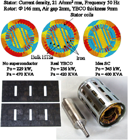
Figure 13. Finite-element method calculation for rotating machine with different relative values and a photograph of the 200 kW superconducting reluctance motor SRE150-340 developed at Oswald Elektromotoren GmbH [57].
Download figure:
Standard image2.3. Hysteresis rotating machines
The mechanical torque of the HTS hysteresis motor results from the repulsion of the magnetic poles, induced into the HTS rotor by the rotating field of the stator winding [62]. The useful torque magnitude is defined by the interaction between the domain and transport currents in the bulk HTS and the rotating magnetic field. It was shown that the torque is linearly proportional to the total hysteresis loss in the HTS rotor and does not depend on the angular velocity of the rotor. A series of HTS hysteresis motors have been designed, manufactured and tested by Kovalev and colleagues at Moscow State Aviation Institute partnered with Institut fur Physikalische Hochtechnologie (IPHT) and Oswald Elektromotoren GmbH. Figure 14 shows a general view of a 4 kW HTS hysteresis motor with a rotation speed of 24 000 rpm. However, for the hysteresis motor, the output power is largely limited by the generation of heat in the rotor [58].
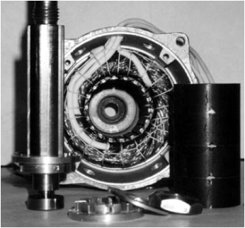
Figure 14. General view of the HTS hysteresis motor with a nominal output power of 4 kW and a rotating frequency of 400 Hz reported by Kovalev et al [58].
Download figure:
Standard imageSystematic research into HTS hysteresis motors was also carried out by Nakamura and colleagues at Kyoto University (figure 15) [63]. First they used a Bi-2223 bulk rotor in the machine, which was changed later into a Sm–Ba–Cu–O bulk rotor for test [64].

Figure 15. Structure of the axial-type hysteresis motor developed at Kyoto University [63].
Download figure:
Standard image3. In situ magnetization of bulk HTS
The in situ magnetization of bulk HTS with trapped fields higher than a permanent magnet is one of the key points for realizing the application of trapped-flux-type rotating machines. It is unthinkable to have to recharge the HTS every time the rotating machine warms up above the HTS operating temperature, not to mention the need to include a cryogenic environment in the assembly.
There are three general techniques for magnetizing bulk HTS: FCM, ZFCM (adiabatic zero-field-cooling magnetization) and PFM. In addition, another method using the flux-pumping concept has received attention recently [65, 66]. The field-cooling method allows complete activation of the flux-trapping capability of the bulk HTS. However, it requires magnetization coils that can provide an ultra-high magnetic field without heat generation. As demonstrated in section 2.1, in some novel configurations FCM has been accepted by using HTS excitation coils.
At the present stage, PFM has received great attention because of its advantages like compactness, mobility and being inexpensive. However, the trapped field BT obtained by PFM is always smaller than that obtained by FC due to the large temperature rise (ΔT) provoked by the dynamical motion of the magnetic flux [67]. The thermal generation can be considered as the sum of the pinning loss Qp and the viscous loss Qv. Qp originates from the flux trapping when the flux penetrates into the bulk HTS and Qv is related to the flux movement. Considerable optimizations have been made in the PFM process to enhance BT, for example the multi-pulse technique, multi-pulse with iteratively magnetizing field (IMRA), multi-pulse with step cooling (MPSC) and combinations of any of these [68–72]. Figure 16 shows the sequence of the MPSC + IMRA technique reported by Fujishiro et al [72]. It can be found that, because of the existing trapped flux in the bulk HTS from the previous pulses, the temperature rise (mainly from Qv) is effectively reduced during the subsequent pulses. On the other hand, lowering the temperature can significantly increase the trapped field due to the Jc enhancement in the bulk HTS. However, with the decreasing of temperature, the pinning energy increases, which leads to a greater Qp; meanwhile, the specific heat of the bulk HTS is decreasing, which will result in a larger ΔT during magnetization. This means that lowering the temperature is not always effective for enhancement of BT. The record of trapped field BT = 5.2 T has been achieved in a 45 mm diameter Gd–Ba–Cu–O bulk at 29 K by MPSC in a solenoid coil [71]. The key point is to establish a concave (M-shape) trapped field profile over the bulk by a relatively low applied pulse field at a relatively high temperature (4.5 T, 45 K) and to optimize the trapped field by a higher applied pulse field at a lower temperature (6.7 T, 30 K).
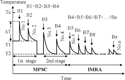
Figure 16. Experimental sequence of the MMPSC + IMRA technique [72].
Download figure:
Standard imageAs described in section 2, vortex-type coils are used in our rotating machine to magnetize the bulk HTS. It was proposed by Ida et al because by using vortex-type coils the magnetic flux would not penetrate into the bulk pellet from the periphery but from the surfaces of the bulk pellet [73]. In this case, the temperature rise is considerably reduced compared to the use of a solenoid coil and is promising for enhancing the trapped field. Very recently, numerical simulations of the PFM process using a vortex-type coil have been carried out by Fujishiro et al and Xu et al, respectively [74, 75]. The simulation results supported the viewpoints of Ida et al (figure 17). According to the simulation results, a vortex-type coil smaller in diameter than the bulk pellet is preferred. Furthermore, a longer pulse application time, which is recognized to be important in the case of solenoid-type coils [76], is not necessary for vortex-type coils. These results are promising for reducing the size of the condenser bank. We have developed a so-called controlled magnetic density distribution coil (CMDC; figure 18), which enables us to arrange the coil type and the magnetic flux distribution along with the starting temperature and the strength of the pulse field. Systematic research results have been reported elsewhere [77–81].

Figure 17. Experimental results (a) and simulation results (b) of the trapped field at the centre of the bulk surface as a function of the applied pulsed field, using the vortex L-coil (L denotes large), vortex S-coil (small) and solenoid coil reported by Ida et al [73] and Fujishiro et al, respectively [74].
Download figure:
Standard image
Download figure:
Standard imageLast but not least, the optimizations of bulk material and rotating machine design are very important to enhance the trapped field. The dynamical motion of the magnetic flux varies in the different growth sections of the HTS grain and is preferentially trapped along the growth sector boundaries [82, 83]. Since flux motion cannot be avoided during the PFM process, a homogeneous Jc distribution in the grain is required. Meanwhile, efficient thermal transfer and the insulation of thermal radiation are required to avoid the flux jump caused by inhomogeneous thermal distribution in the bulk HTS [84, 85].
4. Cooling system
Generally speaking, the basic cooling concepts include direct cooling with cryogens, indirect or conduction cooling, and open-loop cooling with liquid nitrogen [4]. There are also a lot of choices for the refrigeration system, among which the Gifford–McMahon (GM) cryocooler seems to be the most popular. Thanks to its advantages of excellent effective thermal conductivity, ease of construction and robustness, especially for a rotating machine, low production cost etc, a closed-cycle thermosyphon technology was chosen as the cooling system for our rotating machine. The working fluid of the thermosyphons was chosen as neon, liquefying from 24.6 to 44.4 K, with a saturated pressure going from 0.043 to 2.66 MPa. The temperature range, around 30 K, is suitable for making use of the superconducting properties of the bulk HTS. Figure 19 shows a schematic illustration of the neon thermosyphon. A control unit integrated with a gas flow controller and pressure monitor was designed to control the quantity of neon and to monitor the pressure in the condensation chamber (figure 19(b)). A finned heat exchanger made of annealed oxygen-free high-conductivity (OFHC) copper was carefully designed (figure 19(c)) and assembled on the cold head of a GM cryocooler with an OFHC copper heat exchange plate. The operation parameters of the neon thermosyphon including a suitable quantity of neon gas, setting temperature of the cold head and gas pressure in the condensation chamber etc, were optimized during the heat load test (figure 19(d)), during which a 55 W cooling power was obtained at 25 K, approaching the full extent of the GM cryocooler [38]. The neon thermosyphon working as the cooling system of our rotating machine is shown in figure 6(b).

Figure 19. (a) Schematic of the neon-thermosyphon cooling system. (b) Schematic view of the gas control panel. (c) Photo of the OFHC copper fin heat exchanger. (d) Photo of the condensation chamber surroundings: 1, cold head; 2, heat exchange plate; 3, cold head control heater; 4, neon input pipe; 5, condensation chamber; 6, liquid cryogen transfer tube [38].
Download figure:
Standard imageAnother important aspect of the cooling system is thermal insulation, especially the radiation from the stators. In general, except providing a high vacuum environment, the actively cooled screen and multilayer insulation are often utilized in superconducting rotating machines.
5. AC losses of bulk HTS rotating machines
During the operation of bulk HTS rotating machines, the magnetized bulk HTS are subjected to a varying magnetic field, which has a detrimental effect on the trapped field. As a result, the output power of the rotating machine decreases with the decay of the trapped field; that is what is called AC loss. Obviously, suppressing this kind of AC loss is very important for the application of bulk HTS rotating machines. Numerous works have been carried out in this field and most of them are based on the critical-state model [86], the same situation as the magnetization process. Once the magnetized bulks have been exposed to an external magnetic field, the magnetic flux tends to penetrate into the bulk from the surface. Tsukamoto et al supposed that the decay of the trapped field of the bulks is due to the heat generated as a result of flux movements [87]. As a clear proof, a rise of temperature was observed after applying an AC magnetic field parallel to the c-axis of the bulk sample [88].
In addition, it has been demonstrated that the decay of the trapped flux by a perpendicular AC magnetic field to the c-axis is larger than that by a parallel magnetic field to the c-axis [89], attributed to the cross-flow effects. Considerable theoretical approaches have been established to describe these experimental observations. Recently, Vanderbemden et al have reported that the decay in magnetization results from the intricate modification of the current distribution within the sample cross-section [90].
We have carried out a long time synchronous rotation experiment to investigate the AC losses of a bulk HTS rotating machine [91, 92]. The operating temperature was 40 K and the applied AC stator field was 36 mT on average, about 6% of the field trapped in the rotor bulks. It is worth mentioning that Gd–Ba–Cu–O bulks with and without Fe–B–Si–Nb–Cr–Cu amorphous magnetic particles (MP) were assembled on the rotor as field poles for comparison. As shown in figure 20, the decay of the trapped flux mainly took place in the central area of the bulk where the thermal transfer was relatively poor. Therefore, we considered that the AC losses due to heat generation caused by the AC stator field are dominant in this case. The decay of the integrated flux bulks after 5 h of synchronous rotation was 7.2% for the Gd–Ba–Cu–O bulk without MP doping and 4.1% for the doped case. The low operating temperature, where the Jc is much higher and the trapped field is far from saturation, is considered to be important to prevent AC losses. On the other hand, we suppose that the high Jc of MP doped bulk under magnetic field (figure 2) contributes to the better AC performance.
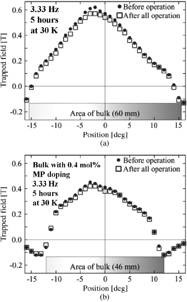
Figure 20. Comparison of the trapped magnetic field distribution before and after a 5 h operation: (a) Gd–Ba–Cu–O bulk without MP doping; (b) Gd–Ba–Cu–O bulk with MP doping [92].
Download figure:
Standard image6. Conclusion
In summary, the high critical current density of bulk HTS enables a compact configuration of HTS rotating machines; this is promising for industrial applications, for example, ship propulsion motors or electrical aeropropulsion. Furthermore, as discussed in this paper, there is still room for the development of bulk HTS rotating machines. Enhancing the flux pinning properties of the bulks from the view of material science or improving the thermal transfer efficiency to prevent the rise of temperature caused by the flux movement during magnetization and AC operation are possible methods of improvement. The most important point is to pursue and realize novel and promising designs, as described in section 2. Since MW-class HTS rotating machines with 1G or 2G wires have already been constructed, design and fabrication of a MW-class bulk HTS prototype is a pressing demand at the present stage.