


Abstract
We analyse the thermal motion of a holographically trapped non-spherical force probe, capable of interrogating arbitrary samples with nanometer resolution. High speed video stereo-microscopy is used to track the translational and rotational coordinates of the micro-tool in three dimensions, and the complete 6 × 6 stiffness matrix for the system is determined using equipartition theorem. The Brownian motion of the extended structure is described in terms of a continuous distribution of thermal ellipsoids. A centre of optical stress, at which rotational and translational motion is uncoupled, is observed and controlled. Once calibrated, the micro-tool is deployed in two modes of operation: as a force sensor with <150 femto-Newton sensitivity, and in a novel form of photonic force microscopy.
Export citation and abstract BibTeX RIS
Introduction
An extended low-symmetry colloidal particle (fig. 1) may be trapped by multiple, holographically generated optical beams [1], such that it is harmonically bound with respect to each of its translational and rotational degrees of freedom. Such a system has clear advantages for applications in force sensing [2, 3], enabling accurate 3D positioning of a tip with nanometric radius of curvature, for point force measurements. The position of this tip can be measured precisely using stereo microscopic video tracking, allowing a form of photonic force microscopy (PFM) to be performed [4]. Use of an extended structure means that the optical trapping field can be separated from the region of the tip-sample interaction, thereby suppressing the problems of beam occlusion and probe tracking that normally inhibit PFM of optically dense media [5, 6]. The operation, calibration and spatial resolution of such an instrument depend on the thermal motion of the trapped particle. Here we present a suitable analysis for a non-spherical probe, or micro-tool, before demonstrating its use as a force sensor.
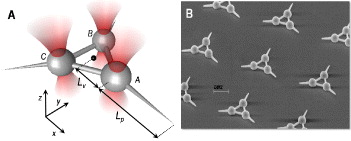
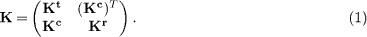
Fig. 1: (Colour on-line) (a) The micro-tool consists of three spherical trapping handles, 5 μm in diameter, with centres separated by 10 μm. An 8 μm tapered tip extends from each sphere. (b) An SEM image showing an array of micro-tools.
Download figure:
Standard imageParticle fabrication and tracking
The micro-tools are fabricated on a glass substrate using a 3D laser lithography system [7] (fig. 1(b)). They consist of three spherical handles, through which the trapping beams pass, connected by thin cylinders and equipped with protrusions for the measurement and application of forces (fig. 1). The micro-tools are removed from the substrate using a micromanipulator, into an aqueus solution of 0.5%Tween-Twenty surfactant, before being injected into a sample cell. Particle tracking is achieved using a high numerical aperture stereoscopic imaging system similar to that described in [8]. By illuminating the sample from two directions simultaneously, and separating the superimposed images collected by the objective lens, the three-dimensional coordinates of spherical objects are recovered by combining two-dimensional position tracking performed on each image [9]. The three-dimensional positions of the micro-tool's spherical handles are found in this manner, and combined to find the position and orientation of the extended particle relative to the lab frame, in real time, at a rate of 1 kHz.
Equipartition theory applied to a rigid body
For small displacements of the micro-tool, the optical force field can be linearised, i.e., fg = −Kq, where fg = (fx,fy,fz,tx,ty,tz) and q = (x,y,z,θx,θy,θz) are, respectively, the generalized force and coordinates, and K = −[∇fg]T is the optical stiffness matrix, evaluated at the equilibrium coordinate. The fi and ti are forces and torques respectively and the θi specify an axial rotation. Optically induced force fields cannot, generally, be derived from scalar potentials [10]. Consequently, K need not be symmetric [11]. However, since the micro-tool is trapped through a set of spherical handles, it inherits the properties of a locally conservative force field, and a symmetric stiffness matrix [12] with the general form:
The sub-tensors, Kt and Kr, relate forces to displacements and torques to rotations, respectively, while Kc and its transpose govern the coupling between rotation and translation. For particular traps, the form of K is further restricted by the symmetry of the system, comprising the optical field and the trapped particle, at mechanical equilibrium.
Since the trapping forces are locally conservative, the equipartition law can be applied, and the thermal energy equated to the elastic trap energy,

(where K is symmetric and I is the unit matrix). K can therefore be evaluated from a measurement of the covariance matrix, 〈q⊗q〉.
A correlation matrix for the system may be calculated by normalising the covariance matrix, for example the correlation between motion in x and y (Cxyr) is given by 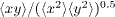 . The inset in fig. 2(a) shows an experimentally determined correlation matrix for a micro-tool similar to that illustrated in fig. 1, trapped with three nominally identical beams. As expected from the system symmetry, the trap is well balanced, and off-diagonal (coupling) terms are minimal (all < 0.15). Inversion of 〈q⊗q〉 enables calculation of a stiffness matrix, K, that is diagonally dominant. Figures 2(a) and 2(b) show these diagonal components as a function of beam power. By virtue of the shape of the focal region of a Gaussian beam, the stiffness coefficients relating to motion in the xy-plane are substantially higher than those associated with motion in the orthogonal, z-direction. Thus, the translational stiffness Ktz < Ktx and Kty, while the rotational stiffness Krθz > Krθx and Krθy. All stiffness coefficients are proportional to beam power, as expected.
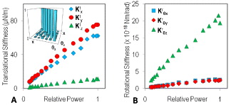
Fig. 2: (Colour on-line) (a) Translational (Ktx, Kty and Ktz) and (b) rotational (Krθx, Krθy and Krθz) stiffness coefficients vs. the relative total power in the optical traps. The inset in (a) shows the absolute correlation matrix (normalised covariance matrix) of the generalized coordinates.
Download figure:
Standard imageThe centre of optical stress
In common with other rigid body problems, the identification of an appropriate coordinate origin simplifies the analysis. The origin is often chosen to permit decoupling of translations and rotations. For example, in free space, the centre of mass is adopted, while in a low Reynolds number fluid, coordinates are referred to a reactive centre coinciding with the centre of hydrodynamic stress (should it exist) [13]. For optically trapped objects it is convenient to define reactive and optical stress centres by analogy. Both optical and hydrodynamic body forces derive from spatial distributions of stress. Using this similarity, an optical reaction centre can be identified relative to an arbitrary origin. If the origin of the particle frame is displaced by the vector a, such that  , then the sub-tensors of K transform as follows:
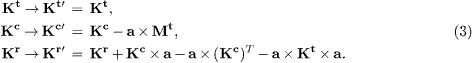
The position of the optical reaction centre can be determined by using the transformation equations (eq. (3)), to find the coordinates of the unique point a = (x0,y0,z0) at which the antisymmetric part of Kc vanishes:

Here,  is the Levi-Civita alternating symbol, and " : " is the double-dot product. A coordinate expansion of eq. (4) is given in the appendix. If the symmetric part of Kc also vanishes at this point, then instantaneous coupling between rotational and translational motion is eliminated, and a is the centre of optical stress. For the system shown in fig. 2, the centre of optical stress coincides with the geometric centre. However, this condition is a consequence of the symmetry of the particle and its optical environment, and is not generally satisfied [14].
Thermal ellipsoids
As the trapped micro-tool undergoes Brownian motion, an arbitrary point within it, at particle frame coordinate rp, experiences stochastic displacements from equilibrium, d, which are normally distributed with covariance 〈d⊗d〉. In doing so, it explores a region, surrounding its equilibrium position, that can be characterized by a thermal ellipsoid oriented with principal axes parallel to the eigenvectors of 〈d⊗d〉, and principal radii given by the square roots of its eigenvalues. 〈d⊗d〉 can be determined by combining the covariance of the generalized coordinates, 〈q⊗q〉, with rigid transforms of the particle frame. When particle frame coordinates are referred to the optical stress centre, the point covariance takes on a suggestive form [12]:

At the optical stress centre itself (rp = 0) the thermal ellipsoid is derived entirely from (Kt)−1, i.e. it is generated by rigid translations of the body alone. Elsewhere, thermal ellipsoids are broadened by rigid rotations that enter via the term −rp × (Kr)−1 × rp. This contribution is disc-shaped, with normal parallel to rp. This behaviour is clearly seen in fig. 3(bii). The thermal ellipsoids are oriented to face the optical stress centre (indicated by the red sphere) which, in fig. 3(bii), is coincident with the geometric centre. The size and anisotropy of the thermal ellipsoids increase with their radial distance from the optical stress centre.
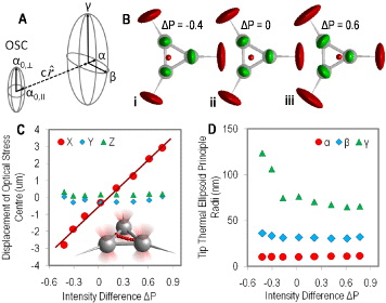
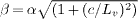
Fig. 3: (Colour on-line) (a) Diagram describing how the shape of the thermal ellipsoid changes, for a point at vector  away from the optical stress centre. (b) Schematics showing experimentally measured dimensions and orientations of vertex (green) and tip (red) thermal ellipsoids (magnified by a factor of 150 relative to the micro-tool) under various trap intensity differences (ΔP). The thermal ellipsoids rotate to face the optical stress centre, which is indicated by the red sphere in each case. (c) The position of the optical stress centre varies linearly along x with ΔP. (d) Variation in the principal radii, α, β and γ, with ΔP, of the thermal ellipsoid of the RHS tip of the probe depicted in (b).
Download figure:
Standard imageThese observations can be formalized by considering the micro-tool as a rigid assembly of identical spheres, which do not interact optically [12]. Consider a micro-tool similar to the one shown in fig. 1(a), with vertices positioned at a radial distance Lv from the origin, probe length Lp, and the trapping stiffness of each sphere equivalent in the x and y directions. As indicated in fig. 3(a), the thermal ellipsoid of the point at the optical stress centre is a prolate spheroid with principal radii a0,∥ in the xy-plane and a0,⊥ perpendicular to it, which depend only on Kt. The dimensions of the thermal ellipsoids of points around the optical stress centre increase with distance c from it. A point displaced by vector  in the xy-plane has principal radii α = a0,∥ orientated parallel to
  ,
,  parallel to
  and
and 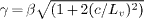 parallel to z. In particular, the spherical handles correspond to a value c = Lv, therefore according to this simple theory, the aspect ratio of the thermal ellipsoids of the handles in the xy-plane will be
  . This compares favorably with an experimentally measured value of 1.39. It should be noted that the principal radii of the handle thermal ellipsoids are independent of length Lv. Therefore the principal axes of the tip thermal ellipsoids (at a distance Lv + Lp from the optical stress centre) remain unchanged if the structure is scaled affinely. However, the size of the tip thermal ellipsoid increases with the ratio Lp/Lv (i.e. a longer probe for a fixed handle separation yields a larger tip thermal ellipsoid). There are clear design implications for the spatial resolution of a force sensor based on such a micro-tool. Since the resolution will be determined by the size of the thermal ellipsoid of the tip of the probe, it will not be improved by scaling the whole structure, but can be by reducing the ratio of Lp to Lv.
Separation of the optical and hydrodynamic centres of stress
Unlike other centres, the optical stress centre is not an intrinsic property of the body but depends on the optical environment; when the optical power is redistributed between the trapping beams, it is moved. Figure 3(a) shows the effect. The total power in the three beams, ptot is fixed, and the power, p1 in one of the traps, is varied relative to the remaining two (p2 in each) which remain equal. Here the relative trapping power ΔP = (p1 − p2)/ptot is varied holographically using the gratings and lenses algorithm, by weighting the complex sum of the hologram patterns used to create a trap at each location. The required weighting factors are calibrated by measuring the stiffness of a microsphere trapped at each power (weighting factor) and location, using

where

and Kx,A is the x-component of the microsphere stiffness in trap A. Krel,y and Krel,z are similarly defined. As ΔP is varied, the optical stress centre traverses the micro-tool. As it does so, the thermal ellipsoids on the spherical handles, and probe tips, rotate to face it (fig. 3(b)). In addition, as the optical stress centre approaches the right hand spherical handle, the effect of rotations on the thermal motion of that handle and of the attached probe is reduced, and the radii of the thermal ellipsoid shrink in the directions dominated by rotations, i.e. perpendicular to the radius (see fig. 3(d)). This provides another mechanism by which the spatial resolution of the micro-tool force probe may be controlled. Redistributing the optical power in this way separates the centres of optical and hydrodynamic stress and exposes the nature of optically induced rotation-translation coupling. This is illustrated by fig. 4, in which the trapped micro-tool is dragged, alternately, in the positive and negative y-directions. The symmetry of the micro-tool dictates that the centre of hydrodynamic stress coincides with the geometric centre and that the resistance matrix is diagonal and invariant with respect to rotation about the z-axis [15]. Consequently, dragging the micro-tool steadily in the y-direction is equivalent to applying a constant force to its geometric centre. When the power in the traps is equal (ΔP = 0), the optical stress centre also coincides with the geometric centre, the fluid exerts a force through both centres and the orientation remains unchanged by the motion, as indicated by the red line in fig. 4(a). In this case there is no rotation-translation coupling, and the covariance or correlation matrix is approximately diagonal (as shown in fig. 2(a) inset).
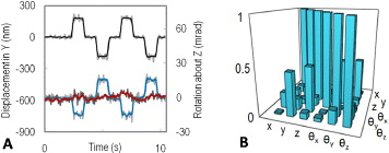
Fig. 4: (Colour on-line) (a) Micro-tool displacements in y (black line, left axis) and θz (red line for ΔP = 0, and blue line for ΔP = 0.65, right axis) during a series of 50 μm/s drags in the ± y-directions. (b) The absolute correlation matrix for the case when ΔP = 0.65.
Download figure:
Standard imageHowever, when the power is redistributed (to ΔP = 0.65 in this example) the force applied by the fluid acts at a distance from the optical stress centre, and the micro-tool rotates into a new equilibrium orientation, which is reversed when the direction of translational motion changes (blue line, fig. 4(a)). The rotational-translational coupling is manifested in the correlation matrix (calculated from thermal motion alone prior to dragging), which has significant peaks for the 〈yθz〉 and 〈zθy〉 terms (fig. 4(b)). A similar behaviour is predicted if the separation between the stress centres is induced by modifying the hydrodynamic resistance, instead of the trap stiffness, for example by modifying the geometry of the micro-tool.
Force sensing and PFM
The use of the micro-tool as a sensitive 3D force sensor is illustrated in fig. 5. A test sample consisting of two 8 μm colloidal spheres adhered to the floor of the sample cell is used, and the probe is introduced from the side (in the direction of the white arrows in fig. 5(di)). Since contact forces act normally, the direction of the measured force reveals the orientation of the surface. Additionally, comparison of the force and torque indicates the precise point of contact, assuming that the latter lies somewhere on the shaft of the probe. Under the application of an external force, eq. (4) gives the location of the mechanical stress centre —the point at which rotational and translational coupling of motion due to optical and external forces is minimised. While the measured forces increase linearly during the approach, the position of the mechanical stress centre shows an abrupt change upon contact, and moves asymptotically towards the contact point. This suggests that the motion of the mechanical stress centre may be used as a highly sensitive indicator of contact, not available from force or torque measurements alone. This mode of operation may be particularly useful when studying softer surfaces, and especially fragile biological samples. Under normal operating conditions (ΔP = 0), the micro-tool demonstrated here is capable of exerting and measuring forces in the range 0.15–10 pN with a spatial resolution defined by a tip thermal ellipsoid of principal axes α ≈ 10 nm, β ≈ 30 nm, and γ ≈ 75 nm. As described above, the operational force range and spatial resolution can be tailored by altering the probe's geometry and varying the relative trapping intensity ΔP.
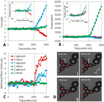
Fig. 5: (Colour on-line) The micro-tool deployed as a force sensor. (a) Components fx, fy and fz of the force experienced by the probe as it is holographically stepped towards, and retracted from, an 8 μm diameter microsphere adhered to the floor of the sample cell. Before contact, the standard deviation of the magnitude of the force measured by the probe is 154 fN, giving an estimate the force sensitivity in this mode of operation. (b) The torques tx, ty and tz, measured during the approach and retraction. (c) The measured position of the optical stress centre during the force curve. The hatched blue line on each graph indicates the step at which contact is made. (d) Stereoscopic (left and right) images of the micro-tool approaching the beads. Red circles indicate trap positions, red crosses indicate the position of the mechanical stress centre. (i) shows the start of the approach, (ii) shows the furthest approach point.
Download figure:
Standard imageFigure 6 shows the micro-tool in operation during a simple photonic force microscope (PFM) experiment. Figure 6(a) shows the outer surface of the volume explored by the micro-tool tip in free space, while fig. 6(b) shows how this volume is modified when the micro-tool is inserted between the colloidal beads. The experimental configurations of these situations are pictured in figs. 6(c) and (d). As indicated above, the great potential of the micro-tool compared with a simple sphere, when performing PFM, is the possibility to operate in optically dense media, without illuminating the specimen.

Fig. 6: (Colour on-line) The coordinates of the micro-tool tip are calculated by applying rigid transformations to the generalized coordinates q. (a) Outer surface of the volume explored by the tip in free space (pictured in (c)). Inset shows an orthographic projection of the volume. (b) Volume explored by the tip when it is confined between two colloidal beads (pictured in (d)).
Download figure:
Standard imageConclusions
We have analysed the thermal motion of a holographically trapped micro-tool, in three dimensions, and explored the implications for novel forms of force microscopy. An order six stiffness matrix was obtained by applying equipartition to the elastic trap energy, thereby calibrating the system. Thermal fluctuations result in discrete parts of the object exploring the interiors of ellipsoidal equiprobability surfaces (thermal ellipsoids) which are arranged about an identifiable centre of optical stress and increase in size and anisotropy according to the separation from the centre. Experimentally observed dimensions of the thermal ellipsoids and displacements of the optical stress centre (moved by varying the relative powers of the trapping beams) can be predicted by modelling the micro-tool stiffness matrix as a rigid assembly of independent stiffness tensors, each of which is associated with a separate trapping handle [12]. Rotation-translation coupling has been seen to arise from the separation of the centres of optical and hydrodynamic stress, indicating the advantages of designing symmetric micro-tools. Using a calibrated sensor of this kind allows point force measurement and photonic force microscopy of optically dense samples, extending the range of samples accessible to investigation with optical tweezers.
Acknowledgments
This work was funded through the EPSRC (UK), and with the support of the Bristol Centre for Nanoscience and Quantum Information. MJM and MJP acknowledge a Royal Society Wolfson Merit Award.
Appendix
A coordinate expansion of eq. (4) is as follows:
