


Abstract
Due to the extreme plasma conditions in Hall thrusters, such as electron temperature anisotropy and non-Maxwellian electron distribution function (EDF), understanding the plasma-wall interaction is a very challenging task. This letter is attempting to study this issue with a two-dimensional particle-in-cell model. It is found that the anisotropic non-Maxwellian EDF makes the electron temperature threshold for the appearance of a spatial oscillation wall sheath much lower than the Maxwellian EDF does. Furthermore, even though the sheath potential drop in the anisotropic non-Maxwellian case is found much smaller than those in Maxwellian cases, the plasma-wall interaction becomes much weaker since the anisotropic non-Maxwellian EDF is depleted at high energies.
Export citation and abstract BibTeX RIS
Introduction
Plasma-wall interaction (PWI) is always the research focus among the Hall thruster community due to its recognized effects on thruster discharge and performance [1–6]. Commonly, the electron distribution function (EDF) is assumed Maxwellian to investigate the PWI problem inside the thruster channel with either fluid [1–4, 7, 8] or hybrid particle-in-cell (PIC) [9, 10] approaches; however, the numerical outcomings [2, 3] are found to present a significant disparity in quantity with the experimental results [4].
The disparity is attributed to the inappropriate assumption of EDF. As the experiments in the early stage have shown, the EDF in Hall thrusters deviates greatly from the Maxwellian form due to the electron-wall interation [11]. Recent kinetic simulations further indicate that the EDF is anisotropic with its normal-to- the-wall component depleted at high energies [6, 12]. Such a depletion of EDF has also been detected in other low-pressure gas discharge devices [13,14]. Therefore, the Maxwellian assumption on EDF is improper to study the PWI problem in Hall thrusters. To evaluate the non-Maxwellian EDF effect, a comparative research with a kinetic model has been made in this letter as shown below.
Different attempts to simulate the non-Maxwellian behavior in Hall thruster discharge have been done [15–17]. Kaganovich et al. have calculated the influence of non-Maxwellian EDF on PWI in Hall thrusters in detail with a 1D (radial) fully kinetic PIC code [15]; the analytical formulas for calculating the plasma flux to the wall, secondary electron flux, plasma potential, and electron cross-field conductivity have been further derived. However, that 1D kinetic model cannot represent the 2D spatial structure of the sheath near the channel wall. Taccognaet al. have focused the 2D (radial and azimuthal) non-Maxwellian behavior on electron anomalous conductivity and instability [16,17], but it seems that they have not stressed the PWI problems sufficiently. Recently, Yu et al. find that the sheath potential oscillates spatially and temporally in the direction parallel to the wall when the temperature of incident electrons with an isotropic Maxwellian distribution is bigger than a critical value (∼27 eV) [18]. It is further illustrated that the anisotropy of electrons with Maxwellian distribution can lower the critical value to about 18 eV [19]. Therefore, it is preferred to study the effect of non-Maxwellian EDF on PWI in the scope of 2D dynamic sheath as is done in this letter.
Model and results
The kinetic model that characterizes the 2D dynamic sheath has been addressed in detail elsewhere [18]. In the model, ions are regarded as a fixed background since the propellant (usually xenon) atom mass are much greater than electron mass; the ion velocity is set equal to Bohm velocity; electrons are assumed unmagnetized since their Larmor radius is much larger than the sheath thickness (on the order of Debye length λD ) for the parameter scale involved in Hall thrusters.
The simulation domain consists of one lateral wall and part of the radial (r) and azimuthal (z) cross-section of Hall thruster channel, as shown in fig. 1. It is assumed that no variation exists along the axial direction. The azimuthal geometry is further simplified as planar instead of annular. The domain dimensions are 0 ⩽z ⩽ 200λD and r0 ⩽r ⩽ r0 + 10λD , where r0 = 0.035 m . Ions and electrons are generated on the plasma-sheath boundary where the electric potential Φ = 0 and a small quasi-neutral region with a thickness of 3λD is imposed. Different from ref. [18,19], the bilateral periodic boundaries are set more reasonable with  . Both ions and electrons are deposited on the wall boundary, and the wall potential is determined by ∂Φ /∂r = σ /2ε0 , where σ is the surface charge density and ε0 is the vacuum permittivity [20].
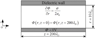
Fig. 1: The simulation domain.
Download figure:
Standard imageSecondary electron emission (SEE) from the wall is the key element to study the PWI problem. Here, as the consequence of one incident electron hitting on the wall, four events are considered: 1) absorption of the incident electron into the wall (in which case the wall acquires the electron's negative charge); 2) elastic scattering of the incident electron by the wall (namely primary backscattering); 3) emission of one secondary electron from the wall; 4) emission of two secondary electrons from the wall. The exact numerical description for these four events can be found in ref. [18]. This SEE model is an improved one from that proposed originally by Morozov [20], in which EVENT 2) is not considered. Recent experimental study shows that EVENT 2) becomes dominant as the electron energy becomes low [21]. It has been demonstrated that the improved model has a better accordance with the experimental data than Morozov's model does [18]. On the other side, ions striking on the wall are totally absorbed with no SEE at all. The emitted secondary electrons are further assumed obeying a half-Maxwellian distribution with a temperature of 1/3 times of the incident electron temperature.
The non-Maxwellian distribution of incident electrons adopted here (see fig. 2(a)) originates from ref. [15]. It can be seen that the high-energy tail is present for the energy distribution F(ε∥) parallel to the wall but it is missed for the energy distribution F(ε⊥) normal to the wall. Using a curve-fitting method, the corresponding analytical expressions of F(ε⊥) and F(ε∥) are

where, a1 = 0.11 , a2 = - 0.302 , a3 = 1.137 ; b1 = 17.83 , b2 = 5.455 , b3 = 0.912 ; c1 = 3.11 , c2 = 4.79 , c3 = 11.71 . The averaged electron kinetic energies  and
and  are then integrated as

which are found close to the corresponding values in ref. [15]. Let  , the normalized electron energy distributions
  and
and  can be obtained as
which are further depicted in fig. 2(b). In the simulation, we keep the normalized EDFs unchanged varying  and
and  . Some other simulation parameters are set as follows. The size of the meshes that discretize the region is 0.5λD × 0.5λD . The time step Δt = 0.1ωep- 1 , where ωep is the electron plasma frequency. The electron density on the sheath boundary is ne = 1 × 10¹⁸ /m3 .

Fig. 2: (a) Anisotropic non-Maxwellian electron energy distribution from ref. [15] and (b) its normalized form.
Download figure:
Standard imageBy implementing the model described above, it is found that the sheath have already turned into the 2D dynamic regime when the EDF follows eq. (2) with both  and
and  only 2.5 eV, as shown in fig. 3. It can be seen that the uniformity of potential distribution in the direction parallel to the wall is destroyed and the spatial oscillation of sheath is raised up. Taking into account that the minimum electron temperature for the appearance of spatial oscillation of the sheath is 27 eV in the isotropic Maxwellian case [18] and 18 eV in the anisotropic Maxwellian case [19], it can be concluded that it is the non-Maxwellian distribution of incident electrons that triggers the dynamical behavior of the sheath.
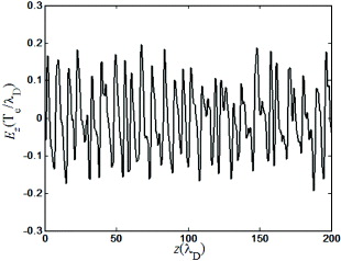
Fig. 3: Distribution of the azimuthal electric field component along the wall surface in the anisotropic non-Maxwellian case with  .
.
Download figure:
Standard imageTo compare the effect of non-Maxwellian EDF with that of Maxwellian EDF on PWI, it is chosen three specific EDFs for simulation, namely, 1) the anisotropic non-Maxwellian EDF as shown in fig. 2(a) with  and
and  according to ref. [15], 2) the anisotropic Maxwellian EDF with electron temperature
  and
and  , and 3) the isotropic Maxwellian EDF with electron temperature
Te = (Te∥ + 2Te⊥)/3 = 24.35 eV. These values are chosen such that the integrated electron temperatures are equivalent for the three cases.
, and 3) the isotropic Maxwellian EDF with electron temperature
Te = (Te∥ + 2Te⊥)/3 = 24.35 eV. These values are chosen such that the integrated electron temperatures are equivalent for the three cases.
As only those electrons with energies greater than the sheath potential drop can reach the wall, it is essential to calculate the wall potential Φw , the electron flux to the wall Γw1, and the electron energy flux to the wall Sw1 . The SEE out of the wall is believed to enhance the electron cross-field conductivity in the discharge channel [2], it is thus necessary to calculate the electron-wall collision frequency νew , the SEE flux Γw2 and the SEE energy flux Sw2 . The SEE coefficient  (=Γw2 /Γw1 ) and the parameters reflecting the electron energy deposition on the wall Λw (=(Sw1-Sw2 )/Sw1 ) are also calculated. Furthermore, to evaluate the cooling effect of SEE on plasma bulk, the incident electron energy flux S01 and SEE energy flux S02 , as well as the ratio Λ0 (=(S01-S02)/S01), on the plasma-sheath boundary are calculated. All the results are listed in table 1.
Table 1:. Calculated parameters on plasma-wall interaction with the three EDFs.
| Parameters | Anisotropic non-Maxwellian | Anisotropic Maxwellian | Isotropic Maxwellian |
|---|---|---|---|
 , Te (eV) , Te (eV) |
 , ,  |
Te⊥=15.58 , Te∥=28.74 | Te=Te⊥=Te∥=24.35 |
| Φw | 2D dynamic regime | −46.08 V ( - 2.96 Te⊥) | −57.91 V (−2.38Te⊥ ) |
 |
9.61×10²¹ | 3.36×10²² | 7.68×10²² |
 |
6.42×10²¹ | 3.02×10²² | 7.26×10²² |
| νew | 4.59×10⁵ | 2.4×10⁶ | 5.49×10⁶ |
 |
0.67 | 0.9 | 0.95 |
 |
4.02×10⁵ | 5.19×10⁵ | 1.14×10⁶ |
 |
2.49×10⁵ | 1.77×10⁵ | 3.67×10⁵ |
| Sw1 - Sw2 | 1.53×10⁵ | 3.42×10⁵ | 7.73×10⁵ |
| Λw (%) | 38.06 | 65.9 | 67.81 |
| S01 (J m- 2 s- 1 ) | 3.63×10⁶ | 4.70×10⁶ | 6.44×10⁶ |
| S02 (J m- 2 s- 1 ) | 3.55×10⁶ | 4.59×10⁶ | 6.19×10⁶ |
| S01 - S02 | 8×10⁴ | 1.10×10⁵ | 2.50×10⁵ |
| Λ0 (%) | 2.20 | 2.34 | 3.88 |
It is not surprising that the sheath oscillates temporally and spatially in the specified anisotropic non-Maxwellian case, as shown in fig. 4. It is known that the sheath is formed to balance the ion flux with the electron flux. As the anisotropic non-Maxwellian EDF holds the most proportion of low-energy electrons among the three EDFs, a smallest sheath potential drop can prevent enough incident electrons to the wall when the ion flux is fixed; therefore, one can find in fig. 4(a) that the potential drop |Φw | is much lower than those in the Maxwellian cases. On the other hand, the classical theory have indicated that the sheath potential drop |Φw | increases as the SEE coefficient  decreases [22]. However, as one can find in table 1, the SEE coefficient
  is the smallest in the non-Maxwellian case where the sheath potential drop is also the lowest; therefore, the classical theory is not valid to analyse the non-Maxwellian situation. The depletion of the high-energy tail of the EDF in the direction normal to the wall, and consequently the fewest energetic electrons knocking on the wall, in the anisotropic non-Maxwellian case is the main cause for the lowest SEE coefficient
  .
.

Fig 4: (a) Azimuthal potential distribution on the wall and (b) its Te⊥ -normalized result.
Download figure:
Standard imageCommonly, on the basis of the same electron temperature, the higher the sheath potential drop |Φw | is, the more incident electrons are reflected back, and the less incident electrons reach the wall. However, the calculation here shows that the electron flux to the wall Γw1 in the isotropic Maxwellian case is two times bigger than that in the anisotropic Maxwellian case although |Φw | in the isotropic Maxwellian case is higher than that in the anisotropic Maxwellian case (see fig. 4(a)). The reason for such a contradiction is that Γw1 depends on the temperature component normal to the wall rather than the integrated temperature. It can be deduced that Γw1 increases as the normalized sheath potential drop |Φw |/Te⊥ decreases; from this point of view, the calculated result is reasonable according to the calculated |Φw |/Te⊥ shown in fig. 4(b). The same principle can be used to understand the remarkable enhancement of the electron energy flux to the wall Sw1 in the isotropic Maxwellian case compared with that in the anisotropic Maxwellian case. Note that according to the analysis above, Γw1 was supposed to be the largest in the anisotropic non-Maxwellian case since |Φw |/Te⊥ is the lowest; however, Γw1 is actually the smallest. It is obvious that the fewest energetic electrons reaching the wall in the anisotropic non-Maxwellian case accounts for that confliction. Consequently, the electron-wall collision frequency νew is the smallest.
A further comparative study has been made to find out whether the electron flux to the wall Γw1 under non-Maxwellian EDF is reduced due to the shape of the EVDF only or due to the oscillations as well. In the presence of sheath oscillations, our simulation shows that the average wall potential  (see fig. 4(a)) and the corresponding Γw1 = 9.61 × 10²¹ m−2 s −1 . Based on the average wall potential
  and the same non-Maxwellian EDF, the electron flux
  in the absence of sheath oscillation is calculated analytically, which is 6.06 × 10²¹ m−2 s−1. One can see that the electron flux under the oscillation regime is obviously larger than that under the steady-state regime. Therefore, the electron flux to the wall is reduced due to the shape of the EVDF only, and the sheath oscillation can increase the electron flux up to 60%. It can be understood as follows. Compared with the steady-state sheath, the spatial oscillation of the sheath gives a chance to those electrons with relatively low energies (lower than
  ) to reach the wall and can also repel those electrons with relatively high energies (bigger than
  ) away from the wall. As the low-energy electron population is remarkably greater than the high-energy electron population for a non-Maxwellian EDF, a greater net electron flux on the wall is obtained.
As SEE flux usually increases with the electron flux to the wall, it is not surprising to find that the SEE flux Γw2 in the anisotropic non-Maxwellian case is the smallest among the three cases; as a result, the electron cross-field conductivity due to SEE is the weakest. Furthermore, as the majority of incident electrons in the anisotropic non-Maxwellian case have low energies, they have the greatest probability to be scattered elastically on the wall (EVENT 2)) with no energy loss; consequently, the integrated energy of secondary electrons is the greatest among the three cases. Therefore, one can find in table 1 that the SEE energy flux Sw2 in the isotropic Maxwellian case is only 1.5 times larger than that in the anisotropic non-Maxwellian case, even though the corresponding difference of SEE flux Γw2 is nearly three times as large as that in the anisotropic non-Maxwellian case. Consequently, the ratio of electron energy flux Λw deposited on the wall in the anisotropic non-Maxwellian case is much less than those in the Maxwellian cases. It can be then understood easily that the cooling effect, referenced by the parameter Λ0, is the smallest in the anisotropic non-Maxwellian case.
In summary, with a two-dimensional kinetic model, the remarkable difference on plasma-wall interaction between the anisotropic non-Maxwellian EDF and the Maxwellian EDFs has been predicted. Compared with those in the Maxwellian cases, the onset of sheath spatial oscillation in the anisotropic non-Maxwellian case needs a very low critical electron temperature (about 5 eV). Furthermore, the electron flux to the wall, the electron-wall collision frequency, the coefficient of secondary electron emission and the electron energy deposited on the wall are the smallest and the cooling effect to the bulk electrons is the smallest in the anisotropic non-Maxwellian case. The depletion of the high-energy tail in the non-Maxwellian EDF accounts for all of the above findings.
Acknowledgement
This work is supported by the National Science Fund for Distinguished Young Scholars under Grant No. 50925625, the Foundation for Innovative Research Groups of the National Science Foundation of China (Grant No. 51121004), and the Fundamental Research Funds for the Central Universities (Grant No. 0903005203189).