


Abstract
This paper presents a complementary approach to the traditional Lorentz and Faraday approaches that are typically adopted in the classroom when teaching the fundamentals of electrical machines—motors and generators. The approach adopted is based upon the Poynting vector, which illustrates the 'flow' of electromagnetic energy. It is shown through simple vector analysis that the energy-flux density flow approach can provide insight into the operation of electrical machines and it is also shown that the results are in agreement with conventional Maxwell stress-based theory. The advantage of this approach is its complementary completion of the physical picture regarding the electromechanical energy conversion process—it is also a means of maintaining student interest in this subject and as an unconventional application of the Poynting vector during normal study of electromagnetism.
Export citation and abstract BibTeX RIS
1. Introduction
A course in elementary rotating electrical machines (motors and generators) is common in physics courses at undergraduate level [1]; this important topic can also be found in pre-university courses and in technical vocational qualifications that contain a reasonable amount of physics content [2, 3]. The author has reason to believe that the topic of electrical machines is typically considered 'less exciting' than other areas of study. This topic is perhaps most practically important to electrical engineers rather than physicists, however the devices typically studied serve as good illustrators of the underlying physical principles [4, 5]. Typically, the traditional methods of teaching how electrical machines fundamentally work are focused around the Lorentz force equation (motors) and Faradays law (generators), ultimately culminating in some 'equivalent circuit' model [6]. This paper outlines an alternative approach based on the use of the Poynting vector in such applications, where it can be seen that calculation of the 'Poynting flow', particularly in the air gap of the machine (the air gap is illustrated in figure 1), provides additional insight into the operation of these rotating electrical machines. This method is shown to be complementary to the traditional methods, permitting the development of a more complete physical picture of the energy conversion process and also aiding the maintenance of student interest in the subject. It is the author's opinion that physical interpretation and understanding of the electromagnetic phenomena exploited in the operation of electrical machinery is of primary importance when teaching the principles of such machines. Of course, mathematics has a role to play, but that mathematics must always aim to enlighten the student with a more complete understanding of the physical picture of the device under study. In this paper, we consider AC rotating electrical machinery, which typically have two modes of operation, motoring and generating.

Figure 1. Industrial induction machine (upper); induction machine section through A–A', quarter model (lower).
Download figure:
Standard image High-resolution imageThe Poynting flow approach is presented as a natural step in illustrating the electromechanical energy conversion that takes place at a steady rate when the machine is in steady state operation. Its use can also be extended to the complex transients, which also take place under fault and transient loading conditions; however, this is beyond the scope of this paper—only the general principles are presented. In the ensuing analysis we consider steady state operating conditions only, machines with linear magnetic circuits, the magnetic cores being considered infinitely permeable  , the exciting currents are considered to be perfectly sinusoidal and the spatial distribution of air gap flux density also perfectly sinusoidal. These are standard considerations in electrical machine analysis such that considerable mathematical difficulty can be overcome. In this paper we consider alternating current electric machinery only, though the Poynting flux method is in general a unified analysis method and can be used for analysing AC and DC rotating machinery, transformers, inductors and other electromagnetic devices.
Firstly a brief review of the 'traditional approaches' to teaching the principles of operation of electrical machines is presented. The concept of the equivalent circuit is then briefly discussed in terms of its usefulness in representing the electromagnetic power flow. The Poynting vector and the associated Poynting theorem is then introduced as a refresher—it is shown that the AC electrical machine is an ideal candidate for application of this approach due to its favourable field characteristics. The Poynting theory is then applied to AC electrical machines, specifically to the air-gap electromagnetic fields introduced through simple vector analysis considering a 2D slide of a radial flux machine—the results are then compared with the conventional Maxwell stress point of view and the key results summarised.
2. 'Traditional' approaches
2.1. Motoring action
The traditional viewpoint [1] when analysing the operation of a motor is usually the application of the Lorentz force equation relating a current carrying conductor immersed in a magnetic field. A typical example is the force produced on the armature of a DC motor or even an induction motor. The electrodynamic force is used to explain the production of torque in electrical machines and is generally written:

Here  is a force on the rotor surface with radius
  the length of the machine is
  the air gap magnetic field is
  with an interaction current
  flowing in a winding to produce a torque,
  This analysis is sufficient to understand the operation of a motor in terms of measureable effects, i.e. the torque produced on the rotor, however the picture is disjointed when we seek to look for energy (or perhaps power) flow in the device. For example, in an induction motor, the B field is produced by the stator and a current density J is developed on the rotor due to that field, then there is a force
  on those conductors and therefore a torque produced on the motor shaft. It is usual to associate an electrical input power to the stator
  and a shaft mechanical power output
  knowing both we can compute energy conversion efficiency, but this perspective does not give a clear physical picture of how the power 'transfers' to the rotor circuits from the stator side circuits and thus how electromechanical energy conversion is performed.
2.2. Generating action
Similarly, when teaching the generator mode of operation of an electrical machine, the traditional approach [1] is usually the application of Faraday's law (electromagnetic induction), typically presented in the context of the synchronous generator, or perhaps a DC generator of the same configuration as analysed in the motoring mode of operation. The usual mathematical presentation is as below:

Here,  is the electric field in a winding, usually considering that the
  field of the synchronous generator is produced by DC coils on the rotor fed by brushes or a brushless exciter. The rotor is then rotated using a prime mover (perhaps a steam turbine) and thus there is a
  present (or there is relative motion of velocity
  in one point of view) and as such the stator coils on the opposite side of the air gap are immersed in this magnetic field, and as such, experience an electric field
  along their axial length due to a changing flux linkage
  This is usually presented as in 'open circuit conditions': if a load is present, the generator will drive electric current (electrical power) to the connected load. In this mode of operation, it is now convenient to associate a mechanical input power to the rotor
  and consider an electrical power output
  Again, this usual analysis does not clearly illustrate the flow of energy, although it is always present in the presentation of these devices that they are electromechanical energy converters and energy conversion, in either direction, takes place (electrical to mechanical/mechanical to electrical), depending on the mode of operation (motoring or generating). These principles are perfectly valid, though it is argued that they are incomplete; they deal with conversion, rather than flow, and to fully understand the device, it is important to understand the complete nature of the device.
2.3. A note on equivalent circuits
In practice, a rotating electrical machine fed by alternating current is a piece of complex electrical equipment. The aim of any introductory course is not to examine and understand the interactions and behavior of each part of the electrical machine, as this is reserved for the specialist machine design engineer, but rather to enable the student to perform calculations on a variety of machines with competency, with a reasonable understanding of the underlying physical principles. Often it is the case that an abstraction is made following their learning of the fundamental physical processes (Lorentz and Faraday). Many assumptions are made [4–6] (linear magnetics, sinusoidally distributed currents, infinitely permeable iron sections, etc) in order to simplify any ensuing analysis. This common abstraction is one of transformation from the 'field' perspective to 'equivalent circuit' perspective—a simpler, but valid approximation of the physical processes which are involved within the machine. In this equivalent circuit abstraction, the magnetic fields present in such machines are typically and conveniently confined to 'lumped element' inductances and/or ideal transformer elements and the Joule losses confined to lumped 'resistive' elements.
The polyphase induction machine [6] is a classic example of where the per-phase equivalent circuit is taught in mainstream undergraduate education and also in widespread use in engineering practice—where an 'ideal' transformer is used to represent power flow across the air gap of an induction machine. There is no doubt that the equivalent circuit representation is a useful one and one of great practical advantage, however, it can be argued that its importance and usefulness in understanding the physical processes and nature of the electromagnetic field distribution that exist within these complex machines is limited. Equivalent circuits themselves give no indication as to the nature and/or consequences of the interaction of electric or magnetic fields that enable electrical machines to function as intended—this knowledge must come first. There is no substitute for equivalent circuits, however it is preferable that the student understands the physical processes involved before embarking on the use of equivalent circuits in order that a fuller understanding of the device that the equivalent is purported to represent is formed.
It is argued by the author that in addition to the fundamental principles such as the Lorentz force and Faraday's law, the Poynting flow should be considered to complete the physical picture before progressing to equivalent circuit representations.
3. The Poynting vector and theorem
In 1884, Oliver Heaviside co-formulated the now named 'Poynting vector' alongside Professor Poynting [7, 8]. It is commonly accepted that the Poynting vector physically represents the directed energy-flux density (i.e. the rate of energy transfer per unit area, or energy density flow) of an electromagnetic field. The Poynting vector,  , in its most common modern form is expressed [9]:

where  and
and  are the electric and magnetic field vectors respectively. This vector follows from the Poynting theorem, an energy-conservation law, where the interpretation of the
  vector is to describe the rate of energy-flux density from a volume (shown here in integral form):
The symbols  have their usual meaning. The theorem states that the Poynting flow across a closed surface with elemental area
  is equal to the rate of work done on a given charge distribution (in electrical machines terms, the real power) plus the electromagnetic energy density in a region of space (the reactive power, in electrical machines terms). Therefore, we can immediately conclude that this appears to be of interest in application to electrical machines due to three distinct reasons:
- 1.The electrical machine is an electromagnetic (electromechanical) device with varying
 and fields present (both temporal and spatial), so we can assume that there is some Poynting flow somewhere.
 - 2.Electrical machines inherently require energy transfer from one volume to another (e.g. stator to rotor)—separated by an air gap where energy conversion appears to take place, either from electrical to mechanical (motor) or from mechanical to electrical (generator).
- 3.Focus is not usually placed in the air gap, but rather the conductors either side of the air gap—we desire to understand the process in between these two regions.


It is clear that the region of immediate interest is the boundary layer of air between the rotary and stationary components of rotary machines (this may also be considered in linear electrical machinery). As students will usually (and should) have covered some elementary electromagnetic theory before tackling electrical machines, an approach to examine the Poynting flow is not unreasonable. Such analysis should be intended as an effort to aid understanding and the presentation of an alternative and complementary viewpoint when venturing into the topic of rotary electrical machines. The viewpoint has been investigated somewhat in the realms of specialist electrical engineering research [10–14], but is by no means a mainstream method of analysis and is practically unknown within the teaching of electrical machinery, even to seasoned academics.
The Poynting vector is now used in the air-gap analysis of an alternating current rotary electrical machine. Use is made of simple vector analysis and the concept of the 'rotating magnetic field', both of which should be familiar to undergraduate students in physics and engineering.
4. AC electrical machinery
Consider a polyphase rotary electrical machine [6] as an electromechanical energy converter, such as the induction motor or synchronous generator. In these machines, a cylindrical rotor rotates in a cylindrical stator, separated by a small air gap—a mechanical clearance. If we consider motoring operation, alternating current electrical power is fed into the stator of the machine and an appropriate system of conductors and magnetic core is designed to set up a rotating magnetic field in the air gap, rotating at an angular velocity (the synchronous speed) about the axis of the machine which is determined by the pole  number and the supply frequency
  Considering the Poynting vector
  it will be shown that the air gap provides a space in which electrical energy can flow into and across an iron–air boundary and flow unimpeded to another air–iron boundary in order to facilitate electromechanical energy conversion.
5. Air-gap Poynting flow
In analysing the Poynting vector in AC machines, the  and
and  fields present must be described—focus is placed on the air-gap region. Considering only a two-dimensional 'slice' or 'cross section' of a radial flux machine (such as the induction machine or the synchronous generator), the air-gap magnetic field vector
  can be described vectorially in a cylindrical co-ordinate system at each point in the air gap as:

where  is a radially directed component and
  is a circumferentially directed component. Note that there is no axial component in
  The 'magnetic flux lines', often used to visualise the field in electromagnetic devices, are contours of constant magnetic vector potential
  this is an auxiliary vector quantity often used for computation in electrical machines. Figure 2 shows the magnetic vector potential plot of a four-pole induction motor, computed using a 2D nonlinear finite element model.

Figure 2. Magnetic vector potential distribution.
Download figure:
Standard image High-resolution imageThe magnetic vector potential is linked to the air-gap magnetic field through the following equation:

It should be noted that in the machine air gap, the permeability  used in the constitutive relation
  is for all purposes equal to vacuum permeability and therefore represents a linear isotropic relation, permitting the use of the principle of superposition. Therefore, it follows from Faraday that there exists an induced electric field in the air gap:


Due to the involvement of  the induced air gap electric field
  is axial in direction
  and it should also be noted that
  as the magnetic vector potential
  is typically a spatial and temporal sinusoidal function:

The magnetic vector potential in the air gap is a travelling wave and its frequency depends on the number of pole pairs  of the machine and the speed at which it travels on the injected electrical frequency
  Figure 3 shows the typical characteristic of the axial component of the magnetic vector potential
  in the air gap of an AC machine. This is the well known 'rotating magnetic field' first described by Nikola Tesla and perhaps most eloquently demonstrated by Tesla's Egg of Columbus. Therefore, it naturally follows from the Poynting theorem that there must be, in a region with
  and
and  in co-existence, an air-gap Poynting flux:

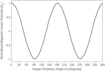
Figure 3. Magnetic flux density distribution.
Download figure:
Standard image High-resolution imageThe axial electric field caused by this time-varying magnetic vector potential is thus used in conjunction with the originating air gap magnetic field intensity to form a Poynting vector—an energy-flux density flow in the air gap of the machine. This flux, in general terms, represents the electromagnetic power reaching the air gap from the stator and therefore the electromagnetic energy transferred in accordance with the Poynting theorem—the flow of energy-flux density across the rotor enclosing surface. Included in this transfer is the proportion dissipated as rotor losses (both DC and AC winding and iron losses) and the proportion being converted to mechanical power at the shaft output, in the motoring case. Two key cases can now be presented to illuminate the fact that there is a Poynting flux in the air gap. The first is the case of the 'unloaded' machine (no mechanical torque applied to the rotor of a motor or an electrical load connected to a generator), where if the air gap is considered smooth and the rotor is a simple high permeable cylinder with no conducting regions or exhibits any saliency, the air gap magnetic field is known to be purely radial when crossing the air gap and thus the Poynting flux can be found, in the steady state, to be purely circumferential in nature as a consequence:

This is a surprising result as it suggests that the energy-flux density is circulating within the air gap. However, the true value of this analysis is only visible when we investigate a practical machine design, such as the induction motor with its embedded rotor conductors short circuited by end-rings in a squirrel cage design or in the case of a synchronous reluctance motor with high rotor saliency. The scene in the air gap of an unloaded machine is presented in figure 4.

Figure 4. Air-gap vectors—unloaded AC machine.
Download figure:
Standard image High-resolution imageIn practical machine designs, any energised rotor conductors induce an additional air gap magnetic field, and in the case of the reluctance motor, the saliency modifies the air gap permeance function away from assumed uniformity—both effects result in perturbing the air gap magnetic field from its purely radial nature when the machine is under load and introduce a circumferential air gap magnetic field component  For example, at the air gap–iron boundary in an induction machine, the conductors consisting of a number of turns (or perhaps solid bars in a caged rotor machine) are placed in slots (figure 1). When a current flows, this source of magneto-motive force contributes to a tangential magnetic field component
  which can be found via the application of Ampere's circuital law around the conductor periphery1
[15]. The introduction of this component in turn alters the Poynting vector as follows:
which can be found via the application of Ampere's circuital law around the conductor periphery1
[15]. The introduction of this component in turn alters the Poynting vector as follows:

The components of the Poynting flow can be calculated:

It is straightforward to see that the axial component of Poynting vector,  , is identically zero. The radial component is of most interest as it is this component that transfers energy across the air gap—the axial electric field
  and the tangential magnetic field in the air gap
  are therefore the key components. The 'loaded' machine scenario is presented in figure 5.
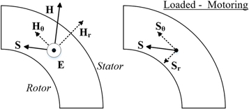
Figure 5. Air-gap vectors—loaded AC machine (motoring).
Download figure:
Standard image High-resolution imageTherefore, in the case of a motor, the Poynting vector is no longer purely circumferential and circulatory in nature, but now is directed at some angle determined by the loading level of the machine, into the rotor, transferring the power loss and the mechanical output power as radiated electromagnetic energy-flux density over the rotor surface. This perspective is an additional viewpoint that is useful in teaching students how AC electrical machinery operates, clearly and explicitly showing the electromagnetic energy transfer across the air gap between the stator and rotor and the necessary conditions required (field components). It is noted that electrical machines appear to be useful only when a circumferential component of an air gap magnetic field exists to create a component of Poynting vector radially inward to the rotor for a motor, or, if we seek to understand generator operation, the vector direction is reversed such that the Poynting vector is radially outward from the rotor surface into the stator, reversing the energy flow. A brief summary of key results for AC rotating machines is provided in table 1 for reference.
Table 1. Key results: air gap Poynting flow.
 direction direction |

|

|

|

|
 direction (w.r.t rotor) direction (w.r.t rotor) |
|
|---|---|---|---|---|---|---|
| Unloaded |

|
Non-zero | Zero | Zero | Non-zero | Circumferential |
| Loaded motor |

|
Non-zero | Non-zero | Non-zero | Non-zero | Tending radially inward |
| Loaded generator |

|
Non-zero | Non-zero | Non-zero | Non-zero | Tending radially outward |
Therefore, the elementary analysis of AC machines using the Poynting vector and the Poynting theorem suggests that in order for an AC machine to facilitate electromechanical energy conversion and for a given machine to maximise the rate of energy conversion, it is the radial component of interest, radiating either inwardly or outwardly from the rotor—depending upon the mode of operation.
The air gap is the medium in which the energy-flux density radiates before impinging on the bounding surface of either the rotor (motor) or stator (generator). Correct integration of the Poynting vector describes the electrical power transferred across the air gap available for conversion—this is best performed with thorough mathematical analysis in complex form and it is beyond the scope of aim of this paper to present such a detailed mathematical analysis of the flow in the air gap. However, to show that the results are consistent with traditional theory, we can consider the Maxwell stress tensor [9]. It is common that the Maxwell stress description of the rotor surface tractive effort is traditionally employed in more advanced electrical machine analysis, and for implementation in finite element models. It can be shown that the rotor surface tangential force density (torque producing component) is written [4–6]:

Here,  is the Maxwell stress tensor distributed over the rotor surface. It is clearly seen that there is no tractive effort upon the rotor surface if the conditions in the air gap are such that
  and hence from the Poynting viewpoint
  This result therefore fully agrees with previous result that
  is required in order to facilitate useful energy transfer across the air gap in rotating AC machines. Without this tangential component, the machine would simply not work as intended. It must be noted that if a more general analysis is performed, radial, tangential and axial components of both the E and H fields will exist. Some of these flows will be of interest, however it is the radial flow that is key to electromagnetic energy transfer across the air gap.
6. Conclusions
This paper has illustrated by the way of simple vector analysis that the Poynting vector approach to electromagnetic energy transfer in common alternating current machines can provide useful insight into the processes that govern machine operation. It is shown that an air gap electric field is induced due to the time-varying magnetic vector potential in that air gap; this axial electric field then interacts with the radially directed air-gap magnetic field to produce a circulating electromagnetic energy flow in the air gap of an unloaded (non-torque producing, lossless) electrical machine: a Poynting vector exists. When the resultant air-gap magnetic field is perturbed by a tangential magnetic field under machine mechanical loading, a radial component of the Poynting vector develops to facilitate electromagnetic energy transfer across that air gap. The existence of a directed electromagnetic energy flow in the air gap of an electrical machine complements the traditional approaches typically adopted in the classroom, and the key results obtained through the Poynting flow analysis can be shown to agree with the Maxwell stress tensor approach. This method of attack can provide a complementary physical picture and provide an unusual exemplar application of the Poynting vector in physics and engineering courses at undergraduate and graduate levels.
Footnotes
- 1 where is the slot opening width, assuming that the magnetic core has Note that changes sign with a change in current direction. For a detailed explanation, the reader is advised to consult [15].


