
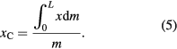
Abstract
Previous work covers building a tower from a stack of homogeneous rectangular plates, each with a maximum shift in displacement. We suggest using plates shaped as curvilinear triangles bounded by segments of power-law functions. The masses of the plates and the position of their center of mass are calculated and measured experimentally after cutting them out from cardboard and aluminum sheets. A computer simulation of the displacement towers is combined with their live building. Individual maximum shifts of the plates in the stack prove to be much bigger the higher the power coefficient of the boundary curves. The resulting total overhang of such a displacement tower may exceed that of a stack of traditionally used homogeneous rectangular cards.
Export citation and abstract BibTeX RIS
1. Introduction
Building of a stable stack of displaced playing cards extending far beyond its pedestal [1, 2] is among the most enjoyable educational projects and hands-on/minds-on science musuem exhibitions. Some ingenious variations of this highly involving and instructive activity have been suggested. Playing cards could be substituted by various, yet still highly symmetrical homogeneous identical objects such as books, journals, coins, wooden sticks or cardboard plates [3–5] stacked on one another to produce a 'leaning tower'. The technique is to first shift the topmost element of the stack horizontally outwards until it remains barely balanced, that is, while its center of mass stays projected onto the edge of the lower plate, figure 1(a).

Figure 1. (a) and (b) How a stack of cards works.
Download figure:
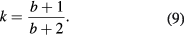
Standard image High-resolution imageFor the case of the standard rectangular plates, the topmost (first) one may be shifted beyond the stack by (almost) half its length. Let us denote this maximum displacement as Δx1 = 0.5L, where L is the length of the plate. When shifting the second consecutive plate in the same direction, one should allow the position of the center of mass of the pair of the two topmost elements to be projected onto the third plate, figure 1(b). As a result, the displacement of the second plate should not exceed the maximum value of Δx2 = 0.25L. Analysis of the maximum possible displacement Δxi of the ith rectangular plate in a stable stack, where 1 ⩽ i ⩽ n is the number of the plate counted down from the top of the stack, is given in [3]. It reveals the harmonic series formula
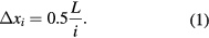
Here the 0.5 coefficient is due to the center of mass of each rectangular plate being in its geometrical center.
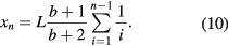
To determine how far the edge of the topmost card in the stack of n rectangular cards may overhang the base of the tower, xn+1, one should sum up corresponding cards' displacements Δxi over an interval 1 ⩽ i ⩽ n − 1, which gives
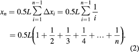
The maximum displacement tower of homogeneous rectangular plates is presented in figure 2. For L = 12 cm and 6 cards we will have x6 = 13.704 cm, which is bigger than the length of the plate L. Thus, the topmost card hangs out noticeably beyond the tower's base.

Figure 2. Displacement card tower at maximum shifts, side view.
Download figure:
Standard image High-resolution imageIt should be noted that the cards are not necessarily shifted in a straight line pattern. Some spectacular designs of a displacement tower include, in particular, self-supporting spiral staircases [6].
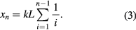
In [6] a theory was suggested of an equilibrium of a stack of identical displaced plates with an arbitrary positioned center of mass. The resulting formula (3) for the topmost plate's maximum overhang is still based on the harmonic series, but the distance coefficient k depends on the center of mass position due to mass distribution in the plates, and/or on their shape:
Thus, for homogeneous rectangular cards the coefficient k = 0.5, while triangular plates will have a coefficient of k = 0.67. Moving of the center of mass from the geometrical center of the plates may allow for bigger shifts of the balanced displacement tower. A rather simplified way to do this consists of attaching identical extra masses such as coins to one of the cards' sides.
In the present work we suggest and analyse the building of a displacement tower from homogeneous diversely shaped plates with the aim of increasing the displacement of the tower's topmost plate (total overhang).
2. Displacement towers built from curvilinear plates
2.1. Centers of mass of power-law curvilinear triangles and of their shifted stacks
To increase the total overhang of a displacement tower built out of fixed length elements, getting the center of mass of the homogeneous building plates closer to one of their sides is required. Leaving this side to be a straight line segment (x = 1 in figure 3), we took for the other boundaries the segments of power-law function
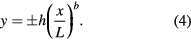

Figure 3. Curvilinear figures used for calculations of center of mass position and in the building of displacement towers.
Download figure:
Standard image High-resolution imageThe resulting plates are all inscribed into the rectangle of length L and width 2h.
Figure 3 shows four such plates for h = 1, L = 1, and power index values b = 0 (straight line boundary, rectangle), b = 0.5 (square root line boundary), b = 1 (straight line boundary, isosceles triangle), b = 2 (parabolic boundary), and b = 3 (cubic boundary).
The position of the centers of mass of the plates, xC, is easily calculated using standard formulas.
Where m is the mass of the chosen figure,
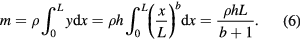
According to (6), the plates' mass is inversely proportional to b + 1, a surprisingly straightforward dependence. Here ρ is the plate's density (mass of the unit of its area). No less beautiful is the expression for the position of the plates' center of mass. To obtain it, first the numerator in (5) should be calculated:
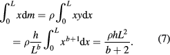
Divided by the earlier determined mass m of the plate (6), it gives, in accordance with (5):
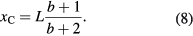
This expression ranges the position of center of mass of the studied curvilinear figures, the closer to its straight line base (line X = 1 in figure 3), the bigger the exponent index b is.
Figure 4 illustrates how the position of the center of mass of the curvilinear plates inscribed into the rectangle of length L = 240 mm and width 2h = 120 mm (sizes used in experimental part of the project) changes with b.

Figure 4. Curvilinear plates bounded by the segments of power-law function, and their centers of mass.
Download figure:
Standard image High-resolution imageWhen used to build a displacement tower, the closeness of the plates' centers of mass to their bases allows for a bigger possible shift of every plate in the stack, and as a result, an increased maximum overhang. Correspondingly, the distance coefficient k in (3) equals to
It may reach a value close to k = 1 at essentially big power coefficients b, in comparison to k = 0.5 for rectangular homogeneous plates (case of b = 0).
The topmost plate's maximum overhang in the stack of n plates (3) is thus given by
Being directly proportional to the value of distance coefficient k, it may be up to (nearly) twice as a big as the maximum overhang of a stack of the same length rectangular cards.
Table 1 contains data on the individual relative shift for curvilinear plates that may be used when building displacement towers. Table 2 presents the maximum displacements of the topmost plate (total overhang) for a tower built from different curvilinear construction elements, depending on the amount of the plates in the stack.
Table 1. Maximum individual relative shifts Δxi/L for variously shaped curvilinear plates. Plates' boundaries are power-law functions  closed with a straight line segment.
| i | Δxi/L | ||||
|---|---|---|---|---|---|
| Rectangular b = 0 | Square root b = 0.5 | Triangle b = 1 | Parabola b = 2 | Cubic b = 3 | |
| 1 | 0.500 | 0.600 | 0.667 | 0.750 | 0.800 |
| 2 | 0.250 | 0.300 | 0.333 | 0.375 | 0.400 |
| 3 | 0.167 | 0.200 | 0.222 | 0.250 | 0.267 |
| 4 | 0.125 | 0.150 | 0.167 | 0.188 | 0.200 |
| 5 | 0.100 | 0.120 | 0.133 | 0.150 | 0.160 |
Table 2. Total overhang of towers built from different curvilinear plates, as a function of their amount n.
| n | xn/L | ||||
|---|---|---|---|---|---|
| Rectangular b = 0 | Square root b = 0.5 | Triangle b = 1 | Parabola b = 2 | Cubic b = 3 | |
| 2 | 0.500 | 0.600 | 0.667 | 0.750 | 0.800 |
| 3 | 0.750 | 0.900 | 1.000 | 1.125 | 1.200 |
| 4 | 0.917 | 1.100 | 1.222 | 1.375 | 1.467 |
| 5 | 1.042 | 1.250 | 1.389 | 1.563 | 1.667 |
| 6 | 1.142 | 1.370 | 1.522 | 1.713 | 1.827 |
As seen in table 2, the maximum overhang of stacked square root, triangular, parabolic and cubic plates sufficiently exceed those of the same number of traditional rectangles ones.
2.2. The building of displacement towers from power-law curvilinear triangles
For educational hands-on activities on building displacement towers, several sets of identical homogenous curvilinear plates were cut from pressed cardboard and from metal sheets with high precision. The photograph in figure 5 presents three stacks (rectangular, triangular and parabolic), including six aluminum plates, with each stack overhanging the desk's edge at maximum displacement. As predicted above, the parabolic stack demonstrates the biggest overhang of the three.

Figure 5. Stack of aluminum plates (from below: rectangular, triangular and parabolic) overhanging the desk's edge.
Download figure:
Standard image High-resolution image
Two scenarios of the building project could be practiced. A direct hands-on activity presumes shifting of the plates without any preliminary knowledge of their limiting positions, and further comparison of the experimentally determined maximum displacements with the values predicted by the theory. In this case students start with the unshifted tower, displace the topmost plate until it barely keeps balance, then displace the lower one and repeat the procedure until all the plates are maximum shifted [7].
In the second scenario, students may be encouraged to first perform the above presented calculations of the positions of centers of mass of differently shaped plates and to find the maximum possible shifts in the stack (table 1). Armed with that knowledge, they build the 'leaning' tower from the ground level up [8], placing curvilinear plates onto one another with the earlier calculated shift.
Both scenarios produce stacks impressively overhanging their bases, or the desk's edge (as shown in figure 5).
3. Final remarks
Students' building of displacement towers using specifically shaped plates proves to be an excellent exercise in calculus and a creative hands-on activity. However instructive and involving the calculations and computer simulation3 of the displacement towers, the climax of the project is to build them live. In the hands-on project, students' draw curvilinear power-law triangles on cardboard or plywood and cut corresponding cards to be stacked into a displacement tower. These kinds of plates can be produced more precisely using a 3D printer. The results of weighing and the experimental determination of the centers of mass of the plates should be compared with the theoretical predictions (equations (5)–(8)). Finally, the displacement towers are built, and they by far overhang the edge of the laboratory desk, and that of a traditional stack of rectangular plates.
Acknowledgments
This work is the result of the project implementation: Research and Education at UPJŠ—Heading towards Excellent European Universities, ITMS project code: 26110230056, supported by the Operational Program Education funded by the European Social Fund (ESF). The authors are grateful to Valeri Shpolyanski for cutting precise aluminum plates for the live experiments.
Footnotes
- 3
Online videos (captured simulations) (stacks.iop.org/PhysED/52/045019/mmedia).
Biographies

Alexander Kazachkov is currently an associate professor of the Department of Physics at V.Karazin Kharkiv National University in Kharkiv, Ukraine. After doing PhD research in solid state and low temperature physics, he started teaching physics in 2000, with his fields of special interest being inquiry-based science education, hands-on physics experiments, and computer modeling. He has been actively engaged in pre-service and in-service teacher training and mentoring of the students' educational research.

Marián Kireš is an associate professor at the Faculty of Science Pavol Jozef Šafárik University in Košice, with a research background in inquiry-based science education and its assessment, pre-service and in-service teacher training and competitions of gifted students. He lectures a physics education course, physics in everyday life and physics problem solving courses.