


Abstract
A Korean fusion energy development promotion law (FEDPL) was enacted in 2007. As a following step, a conceptual design study for a steady-state Korean fusion demonstration reactor (K-DEMO) was initiated in 2012. After the thorough 0D system analysis, the parameters of the main machine characterized by the major and minor radii of 6.8 and 2.1 m, respectively, were chosen for further study. The analyses of heating and current drives were performed for the development of the plasma operation scenarios. Preliminary results on lower hybrid and neutral beam current drive are included herein. A high performance Nb3Sn-based superconducting conductor is adopted, providing a peak magnetic field approaching 16 T with the magnetic field at the plasma centre above 7 T. Pressurized water is the prominent choice for the main coolant of K-DEMO when the balance of plant development details is considered. The blanket system adopts a ceramic pebble type breeder. Considering plasma performance, a double-null divertor is the reference configuration choice of K-DEMO. For a high availability operation, K-DEMO incorporates a design with vertical maintenance. A design concept for K-DEMO is presented together with the preliminary design parameters.
Export citation and abstract BibTeX RIS

Content from this work may be used under the terms of the Creative Commons Attribution 3.0 licence. Any further distribution of this work must maintain attribution to the author(s) and the title of the work, journal citation and DOI.
1. Introduction
As ITER is being constructed, there is a growing anticipation for an earlier realization of fusion energy. A Korean fusion energy development promotion law (FEDPL) was enacted in 2007 to promote a long-term cooperative fusion research and development among participating industries, universities and research institutes. As a following step, a conceptual design study for K-DEMO was initiated in 2012 targeting the construction by 2037.
One special concept discussed for K-DEMO is a two-phased development plan. In its first phase, K-DEMO is designed not only to demonstrate a net electricity generation and a self-sustained tritium cycle, but also to be used as a component test facility. Then, in the second phase, a major upgrade is planned, replacing in-vessel components in order to show a net electric generation on the order of 500 MWe. After a thorough 0D system analysis, the major radius and minor radius are chosen to be 6.8 m and 2.1 m, respectively, considering practical engineering feasibilities [1]. The main machine parameters selected for further study are summarized in table 1.
Table 1. Preliminary K-DEMO machine parameters.
| Parameters | Values |
|---|---|
| Major radius (R) | 6.8 m |
| Minor radius (a) | 2.1 m |
| Divertor operation | Double-null |
| Elongation (κx) | 2.0 |
| Triangularity (δx) | 0.625 |
| Magnetic field (B0) | 7.4 T |
| Plasma current (Ip) | >12 MA |
| Fusion power (MW) | 2200–3000 |
| Net electric power (MWe) | 400–700 |
The K-DEMO device reference point incorporates a double-null (DN) divertor which promotes strong plasma shaping (elongation and triangularity) while forcing the divertor X-point inside the vacuum vessel (VV), close to the plasma. The DN option promotes higher plasma performance with improved vertical position control, and an accompanying reduced machine size when compared with single-null (SN) designs. High availability requires large openings to remove and replace large segments of the in-vessel components. A vertical installation concept will be used to assemble K-DEMO. Taking advantage of the tooling needed to assemble the device and the space above the machine, the K-DEMO is designed with a vertical maintenance. It differs from the SN and multi-module vertical arrangement in the EU, which has relatively close fitting toroidal field (TF) coils. The K-DEMO blanket sectors are subdivided into 16 inboard and 32 outboard sectors. To be in alignment with blankets sectors, the upper or lower divertor is also subdivided into 32 modules, respectively. To allow radial space for the vertical extraction of larger blanket modules, the outboard radius of the TF coil is enlarged, with a space of ∼2.5 m between the blanket modules and the outboard wall of the VV [2].
Concepts have been developed for the major components of K-DEMO including TF magnets, poloidal field (PF) coils, central solenoid (CS), VV and in-vessel components along with the preliminary maintenance scheme as shown in figure 1. The peak magnetic field is about 16 T with the field at the plasma centre above 7 T [3]. These values can be achieved by using high performance Nb3Sn-based superconductors. The advantage of using high magnetic fields is that it allows operation with higher plasma current and density which result in higher fusion power that can be achieved with little difference in the reactor construction cost. The key features of the K-DEMO magnet system include two TF coil winding packs with different conductors, enclosed in the TF case to reduce the construction cost and save space for the magnet structure material. The TF design is constrained by maintenance considerations, leading to a magnet arrangement with large TF coils, which minimize the magnetic ripple, and widely spaced PF coils to accommodate the removal of large in-vessel components modules. In order to minimize wave deflection and maximize efficiency, a top launch high frequency (> 200 GHz) electron cyclotron current drive (ECCD) system is considered as a one of the main candidates for the current profile control and off-axis current drive of K-DEMO. The high magnetic field design is compatible with matching the high frequency ECCD.

Figure 1. K-DEMO device core design features.
Download figure:
Standard image High-resolution imageAmong coolant options for the K-DEMO breeding blanket, helium is less favourable because of its low heat capacity and required high pumping power. Supercritical water is excluded because it presents serious corrosion problems, leaving pressurized water as the most prominent choice for the main coolant of K-DEMO when considering available developed balance of plant technologies. Analysis so far shows that a global tritium breeding ratio (TBR) greater than 1 can be achieved using a water cooled ceramic breeder blanket system [4].
2. Physics assessment
The reference point for the K-DEMO design was selected using a systems analysis [1], based on the data of maximum achievable magnet field strength and size determined from detailed magnet engineering, preliminary blanket build by neutronics analysis, and configuration analysis. The operating point has been defined to provide the smallest size facility giving access to significant operating space for both low electric power (phase I) and high electric power (phase II) phases. The K-DEMO device reference point incorporates a DN diverted plasma and strong shaping, with plasma elongation (κx) of 2.0 and triangularity (δx) of 0.625, to promote higher plasma performance. It is found that within reasonable assumptions electric powers of >150 MWe can be produced in phase I, and electric powers up to 400–700 MWe can be produced in phase II with improved plasma beta and energy confinement, while reducing mission risks due to too limited an operating space or to divertor heat fluxes exceeding technology limits. The maximum toroidal field on the TF coil is taken to be ∼16 T, making the reference toroidal field at the plasma centre ∼7.4 T. This is the target of advanced Nb3Sn superconducting magnet research in Korea.
The Tokamak Simulation Code (TSC) [5] was used to simulate the 1.5D–1D transport of energy and current in 2D poloidal equilibrium geometry—time-dependent evolution from early startup (Ip = 500 kA) to t = 4300 s. Flux surface-averaged transport equations are solved to obtain the temperature profiles, utilizing a modified Coppi-Tang transport model [6, 7] with a prescribed temperature pedestal, given by a correlation fit to EPED1 results [8]. The plasma density profile is prescribed with a peak to volume average of 1.4–1.5 [9], with an edge pedestal and finite separatrix density at 0.35 times the central value. The discharge parameters are transferred from TSC to TRANSP [10] for high fidelity heating and current drive (H&CD) analysis. In order to raise the radiated power to a significant level argon and tungsten are included at 0.1% and 0.001%, respectively, of the electron density. Profiles of plasma current density, input power, and radiation losses in the fully relaxed flattop plasma condition are shown in figure 2. With the high toroidal field and high electron central temperatures, the cyclotron radiation loss is significant, amounting to ∼42 MW with a 90% reflectivity assumed for the first wall.

Figure 2. Profiles of plasma current density, input power and radiation.
Download figure:
Standard image High-resolution imageThe H&CD systems on K-DEMO are critical to driving the plasma current and sustaining the burn state, and partially providing the 100% non-inductive current in the flattop burn in combination with the bootstrap current. Five systems are studied: lower hybrid (LH) waves, neutral beams (NBs), ion cyclotron (IC) conventional fast waves, electron cyclotron (EC) waves, and helicon waves. Although the basic performance characterization varies according to the precise operating point and the choice of heating/current drive systems, the total H&CD power expected to be required for K-DEMO is in the range 80–120 MW, based on systems analysis.
LH waves can drive current off-axis and the accessibility of these waves is very good at the high toroidal field side and low density of K-DEMO. A frequency of 5 GHz is chosen to avoid alpha particle absorption, and this is low enough to avoid excessively small waveguide dimensions. The highest CD efficiency γ(= n20RoIcd/PLH) found in the K-DEMO study is 0.22 A W−1 m−2. Launching LH off the midplane increases the efficiency by about 20% compared to the midplane. The power density associated with a passive-active multi-junction (PAM) launcher, which has been demonstrated [11, 12], is 20 MW m−2. If LH provided all the H&CD, it would require 86 MW, so 4.5 m2 of the first wall would be required for the waveguide launcher, not counting space required for support and cooling structures.
The use of NBs, although common and highly reliable on present tokamak experiments, is typically avoided in power plant designs due to the complications of fitting the drift duct into the fusion power core, and the unimpeded flux of neutrals streaming up the drift duct toward the neutralizer and source. Nevertheless, a negative-ion NB with particle energy ∼1 MeV, like that proposed for ITER, could provide customized profiles of H&CD with high efficiency in the K-DEMO plasma with a density ∼1.0 × 10²⁰ m−3, and central temperatures of ∼40 keV. The ITER NB characteristics [13] have been adopted for the survey calculations. Most of the neutral beam current drive (NBCD) will be needed at intermediate radii, 0.2 < r/a < 0.65. This is most conveniently achieved by injecting the NBs above or below the midplane, while maintaining a horizontal orientation for the beamlines. The resulting CD efficiencies γ are in the range of 0.3–0.4 A W−1 m−2, or Icd/Pb = 0.04 − 0.06 A W−1, with the higher efficiencies at larger r/a where the density is lower. This is attractive for driving large amounts of current and the radial location is not restricted, so NBs can fill the current drive gap between the central deposition of ion cyclotron range of frequencies (ICRF) fast waves at r/a < 0.25 and LH wave deposition at r/a > 0.65. The IC, EC and helicon H&CD configurations will be assessed in future work.
The uncertainties from physics and technologies in the K-DEMO analysis highlight topics requiring continued R&D. Virtually all points in the found operating space have high plasma density, approaching or exceeding the Greenwald density, so this regime must become more routine on experimental tokamaks to confirm operation of high performance steady state plasmas at such densities. High radiated power fractions in the divertor are required to disperse the combination of alpha and injected power from the plasma. Divertor regimes like this are not well established experimentally, and increased emphasis on both experiments and simulations are needed. Operating at higher normalized beta can allow a more compact tokamak with higher fusion power, and research into the requirements to access such regimes needs to continue. Regarding technology, the thermal conversion and H&CD wall plug efficiencies contribute significantly to the facility size and power flow in the plant. Higher steady state heat flux capability in the divertor can also expand the available operating space, although more accurate loading descriptions are required to optimize such systems. The continued development of low temperature Nb3Sn superconductor will enhance the accessible operating space and magnet reliability.
3. Magnet system and structural assessment
The K-DEMO magnet system consists of 16 TF coils, 8 CS coils, and 12 PF coils. Internally cooled cable-in-conduit conductors (CICCs) are used in all of the K-DEMO magnets. Key features of the K-DEMO magnet system include the use of two TF coil winding packs, low field (LF) coil and high field (HF) as shown in figure 3. A high current density Nb3Sn strand [14] is used for the TF magnets and the required amount of total Nb3Sn strands for HF and LF coils are ∼450 tons and ∼280 tons, respectively. The space between LF coil and HF coil in the outboard side of the TF magnet is used for joints, turn transition, helium feed-throughs and magnet leads. The coils are serially connected and the nominal current of TF magnet is ∼65 kA and the stored magnetic energy is over 50 GJ with a magnetic field over 7 T at the plasma centre. The insulation thickness for each CICC is designed to be 1.6 mm, which consists of 0.1 mm Kapton tape with coverage of 400% and 0.3 mm S-glass tape with coverage of 400%. The temperature margins for both conductors are well above 1 K and the estimated hot spot temperatures are less than 100 K.
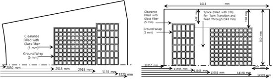
Figure 3. Inboard (left) and outboard (right) cross-section of TF magnet.
Download figure:
Standard image High-resolution imageA total of eight identical CS modules will be placed with a gap of 104 mm and can provide a volt-seconds swing (half swing) of ∼83 Wb. The magnetic field at the centre is about 11.8 T and the peak field is ∼12.2 T, when a maximum current of 42 kA is applied. One CS module is made of four CICC units of ∼880 m length and has 24 layers and 14 turns per layer. An ITER-type Nb3Sn strand will be used for the CS modules and the required amount of total Nb3Sn strands for eight CS modules is ∼125 tons. The temperature margins for CS CICC are also well above 1 K and the estimated hot spot temperatures are less than 100 K. The insulation thickness for CS CICC is 2.0 mm, which consists of 0.1 mm Kapton tape with coverage of 400% and 0.4 mm S-glass tape with coverage of 400%.
The PF coil system consists of 12 coils, PF1-6 upper and lower. PF1-4 coils have eight turns per layer and 20 layers. PF5 coils are divided by two, considering the limitation of unit CICC length and each module has six turns per layer and 36 layers. PF6 coils are made of single CICCs of ∼770 m unit length and have two turns per layer and four layers. An ITER-like low ac loss Nb3Sn strand will be used for the PF1-4 coils and the required amount of Nb3Sn strands is estimated to ∼90 tons. A NbTi strand is adopted for the PF5-6 coils and the required amount of NbTi strands is also ∼90 tons. Here again, the temperature margin is above 1 K and the hot spot temperature is less than 100 K. The insulation scheme for PF coils is same as that for the CS coils. The complete K-DEMO magnet system is shown in figure 4.
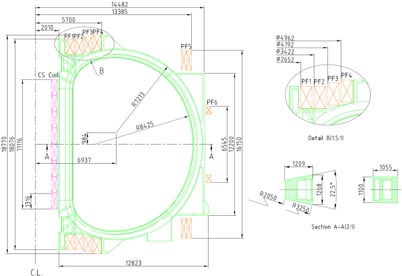
Figure 4. Overall magnet system configuration.
Download figure:
Standard image High-resolution imageThe preliminary CICC design parameters are listed in table 2. Figure 5 shows the dimensions of CICCs including the insulation and the photos of test CICC fabrication are shown in figure 6. No significant issue was found in the test fabrication.
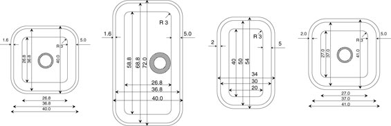
Figure 5. Dimension of CICCs in mm unit (from the left side TF LF, TF HF, CS, PF CICCs).
Download figure:
Standard image High-resolution image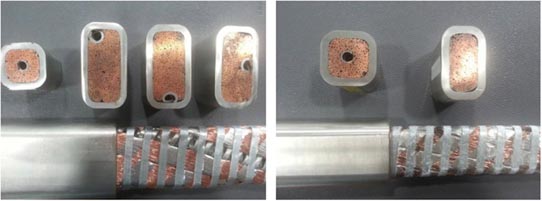
Figure 6. Test fabrication of CICCs for TF (left), PF, and CS (right).
Download figure:
Standard image High-resolution imageTable 2. Preliminary CICC design parameters.
| Parameter | TF HF | TF LF | CS | PF1-4 | PF5-6 | |
|---|---|---|---|---|---|---|
| ▪ Cable pattern | (3SC) × 4 × 5 × 6 × 5 + helical spiral | (((2SC + 2Cu) × 5) × 6 + 7Cu) × 6 + central spiral | (2SC + 1Cu) × 3 × 4 × 4 × 6 + no cooling spiral | (2SC + 1Cu) × 3 × 4 × 4 × 5 + central spiral | ||
| No. of SC strands | 1800 | 360 | 576 | 480 | ||
| No. of copper strands | — | 432 | 288 | 240 | ||
| Spiral dimension (mm) | ID 7/OD 12 | ID 7/OD 9 | — | ID 7/OD 9 | ||
| ▪ Void fraction (%) | 27.1 | 26.0 | 36.6 | 32.5 | ||
| ▪ Strand type | High Jc (> 2600 A mm−2) Nb3Sn | ITER type (Jc ∼ 1000 A mm2) Nb3Sn | NbTi Strand | |||
| Strand 0.82 mm diameter | Strand 0.82 mm diameter | 0.82 mm diameter | ||||
| ▪ Cu/non-Cu of strand | 1.0 | |||||
| ▪ Insulation | 1.6 mm (including Voltage Tap) | 2.0 mm (including Voltage Tap) | ||||
| ▪ Jacket thickness (mm) | 5.0 | |||||
| ▪ Twist pitch (mm) | ||||||
| 1st stage | 80 ± 5 | 80 ± 5 | 27 ± 5 | 35 ± 5 | ||
| 2nd stage | 140 ± 10 | 140 ± 10 | 45 ± 10 | 75 ± 10 | ||
| 3rd stage | 190 ± 10 | 190 ± 10 | 85 ± 10 | 135 ± 10 | ||
| 4th stage | 245 ± 15 | 300 ± 15 | 150 ± 15 | 285 ± 15 | ||
| 5th stage | 415 ± 20 | — | 385 ± 20 | 410 ± 20 | ||
| ▪ Wrapping tape | ||||||
| Sub-cable wrap thickness | 0.08 mm, 40% coverage | |||||
| Sub-cable wrap width | 15 mm | |||||
| Cable wrap thickness | 0.4 mm, 60% coverage | |||||
| Final wrap width | 7 mm | |||||
The global structural adequacy of the K-DEMO magnets is being assessed at this stage to guide the allocation of space between steel structure and other elements, as feedback to the iterative design development process. The finite-element method (FEM) model of the magnet system appearing in figure 7 was created from the CAD design data, and magnetic fields and Lorentz forces were calculated from a reference equilibrium at full magnetic field and performance. Allowable stresses were developed based on structural properties of the proposed TF coil case material (316 stainless steel). Applying criteria according to the ITER Magnet Structural Design Criteria document [15], and based on minimum properties, the primary membrane stress allowable at the 4 K operating temperature is 666 MPa, two-thirds the ultimate yield strength. With a primary membrane allowable of 666 MPa, the bending allowable is 1.5 times this value (999 MPa).
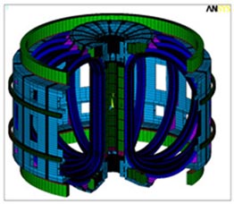
Figure 7. Magnet system FEM model with graphical symmetry expansion (only one TF coil is actually modelled).
Download figure:
Standard image High-resolution imageStresses and deformations were calculated using the ANSYS code. Initial calculations showed the inner leg of the TF coil to be over-stressed, as shown in figure 8, where small local areas of the inner leg exceeding 900 MPa can be seen as gray areas. Bending stresses in the inner corners of the TF of up to 930 MPa should satisfy the bending allowable of 999 MPa. It is argued that the primary stress is around 860 MPa in the yellow and brown contours seen in figure 9. This is a Tresca stress which is basically the absolute sum of the wedging or vault pressure and the vertical tension from the bursting load. This exceeds the 666 MPa allowable by about 30%. Use of ITER minimum properties may be overly conservative.

Figure 8. TF coil case stress distribution contoured to 900 MPa maximum.
Download figure:
Standard image High-resolution image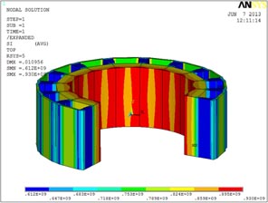
Figure 9. Details of TF inner leg stress, contoured to maximum inner leg stress.
Download figure:
Standard image High-resolution imageVarious analytic and design options were investigated to resolve the static overstress condition. The addition of structural reinforcements to the outer leg and horizontal legs of the TF case did not sufficiently reduce the inner leg stress. Likewise, increasing the wall thickness in the wedged 'nose' of the case by 10 cm (25%) was insufficient, so an initially surprising result is explained by the fact that the winding pack itself contributes substantially as well. Reduction in the toroidal field strength to 6 T would bring the stresses into compliance with a 666 MPa primary membrane allowable.
Structural design codes allow various options for assessing compliance with stress allowables and evaluating the load carrying capacity of a structure. One such option is to perform a detailed, non-linear analysis that accounts for elastic–plastic behaviour, frictional sliding, and large displacement to determine the limit load on the structure. The limit load is that load which represents the onset of a failure to satisfy the normal operating condition. The structure is considered adequate if the limit load exceeds the normal load by a factor of safety greater than 2.0. To investigate this method for K-DEMO a test load of 2.0 times normal was applied. The primary stress increased by only 12% but the strains are substantially higher. Figure 10 shows the case strains to be about 1.2% ; the strains in the superconductor would be similar. The acceptability of this level of deformation in the superconductor would have to be confirmed. With the loads removed, a permanent deformation in the structure of up to 10 cm is seen for this artificial loading scenario. Significantly, the deformations are bounded and the analysis converges to a solution, meaning that while the structure deformed it did not fail. Such a result demonstrates adequate margin. Rigorously, the exercise would have to be extended to address insulation failure, superconductor breakage, and other failures.
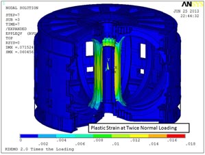
Figure 10. Plastic strain in the TF inner leg with an artificial load of 2.0 times normal.
Download figure:
Standard image High-resolution imageSpecific heats of 316 stainless steel can have higher yields, and with some R&D it is expected that this will be improved. It is expected that such improvements, in combination with a more detailed assessment of the design features that are carrying primary loads, will support the current sizing of K-DEMO.
4. In-vessel components
The blanket and divertor systems are designed as self-standing structures to mitigate interfaces between VV and in-vessel components. Blanket sectors are toroidally subdivided into 16 inboard sectors and 32 outboard sectors (see figure 11), to allow the maintenance of in-vessel components through vertical ports [3]. A segmented semi-permanent structure forms a strongback for supporting disruption loads, providing shielding for gaps between blanket sectors and an alignment system for plasma-facing components. The total area of openings for diagnostic devices, H&CD systems must be limited to meet the global TBR greater than 1.0; an estimate of 26.3 m2 is used, based on previous reactor studies.

Figure 11. Blanket toroidal segmentation −22.5° toroidal blanket inboard and outboard sectors.
Download figure:
Standard image High-resolution imageEach blanket unit consists of tungsten plasma-facing first wall, layers of breeding parts, cooling channels, tungsten passive stabilizer, and manifolds, as shown in figure 12. A thin layer of vanadium is placed as an interlaying material between tungsten first wall and reduced activation ferritic martensitic (RAFM) structural material. Ceramic breeder pebbles of lithium ortho-silicate (Li4SiO4) are used as a mixture with beryllide (Be12Ti) neutron multiplier pebbles. Neutron shields exist in front of the blanket supporting structures and ∼30 mm thick tungsten passive stabilizer plates are placed between the breeding layers and the shield.

Figure 12. A concept view of an indicative blanket module.
Download figure:
Standard image High-resolution imageThe layer configuration of a blanket module is optimized by using the MCNP6 code [16] with the help of a CAD interface code MCAM [17]. A global TBR of ∼1.0 was achieved so far with the varying thicknesses of 10 layers of mixed Li4SiO4 and Be12Ti pebbles. With ∼450 mm of boron carbide (B4C) or ∼600 mm of 2% borated 316 stainless steel in combination with tungsten carbide (CW) balls in supporting structures, the nuclear heating in the TF coils could be reduced below 10 kW [4].
Thermo-hydraulic analyses on the developed concept of blanket module are performed to find the optimal flow path of coolant and to verify that the solid structures and coolant are operated within their allowable temperature ranges. The ANSYS/CFX code is used. Figure 13 shows that solid materials such as tungsten, RAFM and pebbles are operated within their allowable temperature ranges, ⩽900 °C, ⩽700 °C and ⩽550 °C, respectively. Water coolant is also operated as satisfying a pressurized water reactor (PWR)-like condition −15 MPa, inlet temperature 290 °C and ΔT = 40 °C.
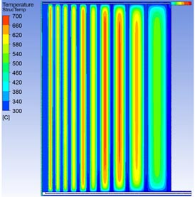
Figure 13. Temperature distribution of breeder and neutron multiplier pebbles, and RAFM parts (mostly shown blue) for a blanket module.
Download figure:
Standard image High-resolution imageThe divertor system has upper and lower divertors with symmetry. To be in line with the blanket toroidal segmentation for vertical maintenance, upper and lower divertors are also subdivided into 32 toroidal modules. The horizontal removal of divertor modules is allowed in the presence of blanket modules through the window prepared in the outboard blanket sector.
The upper or lower divertor comprises an inboard target, a central part, and an outboard target (see figure 14). The divertor target geometry is configured to maximize the breeding area of blanket and to tilt the targets at 10° and 11.5°, for outboard and inboard targets, respectively, against the corresponding separatrix field lines to accommodate the conceived engineering limit of 10 MW m−2 of a peak heat flux. The inlet/outlet cooling manifold for each 11.25° module delivers the water coolant to the outboard target, the central part, and the inboard target in a parallel manner.
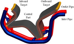
Figure 14. A concept view of a divertor module.
Download figure:
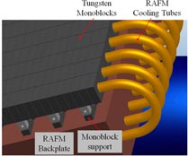
Standard image High-resolution imageThe same concept is used for the inboard and outboard targets. The plasma-facing surface is covered with tungsten mono-blocks connected by the passing RAFM cooling tubes, which comprises an high heat flux (HHF) unit (see figure 15). To avoid cracking on the plasma-contacting face of the tungsten by the high thermal load, each mono-block sizes ∼30 mm (toroidal) × ∼ 12 mm (poloidal) × ∼ 30 mm (thickness). A thin vanadium interlayer exists between the tungsten mono-block and RAFM cooling tube. HHF units are supported from a water-cooled RAFM backplate by using the connecting pin mechanism. Cooling channels exist within the backplate. The heat flux in central part modules is much lower than inboard or outboard targets and the central part module has a different structure. The grooved tungsten plate, to avoid surface cracking, is bonded to the RAFM backplate through a thin vanadium interlayer. The cooling channels are contained in the RAFM backplate.
Figure 15. A detailed view of the outboard target to show high heat flux (HHF) units.
Download figure:
Standard image High-resolution image
Thermal-hydraulic analyses for the divertor targets using ANSYS/CFX code verify that coolant and structural materials operate within their allowable temperature ranges [4].
5. Conclusions
The conceptual study on the Korean fusion demonstration reactor (K-DEMO) started in 2012, based on the National Fusion Roadmap released in 2005 and the FEDPL enacted in 2007. The preliminary concepts of the main tokamak components have been developed for high availability operation with a vertical maintenance scheme. The main machine parameters and operating space were chosen through system analyses. Preliminary feasibility studies on lower hybrid current drive (LHCD) and NBCD were performed. H&CD analyses by IC, EC and helicon waves will be continued for the development of the plasma operation scenario. Pressurized water is the prominent choice for the main coolant of K-DEMO. The ceramic breeder blanket system achieves a global TBR ∼1.0 so far. Preliminary analyses show ∼10 MW m−2 of peak heat flux can be handled at double-nulled divertor targets.
Acknowledgments
This work is supported by the Ministry of Science, ICT and Future Planning, the Republic of Korea. The authors would like to thank the Chinese FDS Team for providing the MCAM code for the neutronics analysis on K-DEMO.