


Abstract
To enhance the core heating efficiency in electron-driven fast ignition, we propose fast-electron beam guiding using externally applied longitudinal magnetic fields. Based on particle-in-cell simulations for FIREX-class experiments, we demonstrate sufficient beam guiding performance in collisional dense plasma by kilotesla-class external magnetic fields for the case with moderate mirror ratio (⩽10). Boring of the mirror field was found through the formation of magnetic pipe structure due to the resistive effects, which indicates a possibility of beam guiding in high mirror field for higher laser intensity and/or longer pulse duration.
Export citation and abstract BibTeX RIS
1. Introduction
The Fast Ignition Realization Experiments project (FIREX project) is now being conducted using the Gekko XII + LFEX laser system at the Institute of Laser Engineering, Osaka University [1]. Detailed analysis of recent experiments [2, 3] and integrated simulations [4] showed very low core heating efficiency: i.e., the energy coupling of the heating laser to the imploded core is less than 1%. The main factors preventing efficient heating are (1) too high fast-electron energy and (2) too large beam divergence. The fast-electron energy could be controlled by eliminating pre-plasma generation and by using a heating laser with shorter wavelength. As for the beam divergence, however, it is difficult to control the angular spread of fast electrons since laser–plasma interactions are strongly non-linear phenomena. Instead of reducing the angular spread, some ideas for guiding the fast-electron beam with large angular spread have been proposed, e.g. a double cone [4–6] and resistive guiding [7–13]. These ideas are based on using self-generated magnetic fields. A guiding concept using externally applied longitudinal magnetic fields has also been proposed [14–16]. In the present paper, on the basis of two-dimensional (2D) particle-in-cell (PIC) simulations, we demonstrate the effects of external magnetic fields on the fast-electron generation and transport in the fast ignition condition.
When sufficiently strong longitudinal magnetic field is applied, the electrons' motion in the direction perpendicular to the beam propagation is limited, and they move along the magnetic field lines since the fast electrons are trapped by the magnetic field lines. Thus, beam guiding can be expected. To evaluate the required magnetic field strength for beam guiding, we have carried out 2D collisionless PIC simulations for fast-electron generation and propagation in a fully ionized carbon plasma with the electron number density of 100ncr(ncr is the laser critical density) [17]. The simulation results show that fields of several kiloteslas are required for beam guiding in FIREX experiments [1], where the heating laser intensity is 1019–1020 W cm−2. In the simulations, however, the longitudinal magnetic fields were uniformly applied and the pulse duration was only 100 fs. For more practical study, in the present paper, we carried out simulations including the collisional effects and considering the converging fields and longer pulse duration. In the following, we discuss (1) the collisional effects and (2) the converging field effects based on the results of 2D collisional PIC simulations.
2. Guiding effects in collisional plasmas with uniform magnetic fields
To evaluate the collisional effects on beam guiding by external fields under picosecond order relativistic laser–plasma interactions, we carried out 2D collisional PIC simulations using the relativistic electromagnetic PIC code PICLS [18]. The simulation conditions are shown in figure 1. The spatial resolution is 50 cells µm−1, which is small enough for the collisional PIC simulations [19]. The escaping boundary condition is adopted for particles and fields on both boundaries (x and y). The target is a fully ionized solid-density carbon foil. The mass density is 1.1 g cm−3 and the electron number density ne is 300ncr. The exponential-profile pre-plasma with scale length of 3 µm is attached to the target front surface. The p-polarized (i.e. electric fields in the x–y plane) laser pulse with the wavelength of λL = 1 µm and the peak intensity of IL = 3 × 10¹⁹ W cm−2 is normally irradiated on the target surface. The transverse intensity profile is Gaussian with a spot size of 6 µm FWHM (full-width at half-maximum). The laser focal plane is x = 8 µm, corresponding to the laser critical density plane. The laser intensity rises to the peak value in 9τL, where τL is the laser period. After this the laser amplitude is kept constant for 300τL, and then is dropped to zero in 9τL. A typical simulation time is 400τL, which corresponds to about 1.3 ps for λL = 1 µm. The external magnetic field is uniformly applied in the x direction. The simulations were carried out by varying the applied magnetic-field strength Bx,ext.
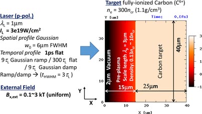
Figure 1. Conditions for 2D PIC simulations.
Download figure:
Standard image High-resolution imageIn figure 2, the spatial profiles of fast-electron energy density and magnetic field structure are shown for Bx,ext = 3 kT. In this case, most of the generated fast electrons are trapped by the longitudinal magnetic fields and then flow along the magnetic field lines. Then the beam does not diverge with the propagation. In addition, it is found that the longitudinal magnetic field, which is initially 3 kT and uniform, becomes weaker (down to less than 1 kT at the beam axis) in the central beam axis (around y = 20 µm). In the region around the beam edge, on the other hand, the longitudinal component is intensified (reaches ∼4 kT). In addition, the magnetic fields in the z direction (∼1 kT) are generated around the beam edge in a direction to confine the electron beam. Therefore, a 'magnetic pipe' [15] like structure is formed. This magnetic field evolution is basically due to the resistive effects, since these structures cannot be observed in collisionless simulations. For discussion of B-field evolution in the dense collisional region, the simplified resistive model is widely used. In this simplified model, the temporal evolution of magnetic fields in the collisional region is described using Faraday's law
 and Ohm's law for the bulk plasma
 (η and
 are the plasma resistivity and the bulk electron return current density) and by assuming quasi-current neutrality
 (
(
 is the fast-electron current density):

For Bx and Bz components in 2D plane geometry are
The generation of Bz collimating the beam comes from
 around the beam edge, as was previously reported [20–25]. The temporal evolution of Bx comes from the gyration motion of fast electrons due to the longitudinal magnetic field. The gyration motion of fast electrons drives the currents in the z direction, which induces the resistive electric fields in the z direction. As a result, due to the transverse gradient of Ez, Bx is weakened around the beam axis and is intensified around the beam edge. In the collisionless case, reduction of Bx around the beam axis is observed, but is smaller than that in the collisional case. Enhancement of Bx and generation of collimating Bz around the beam edge are slightly observed. In the collisional plasma, thus, the fast-electron beam can be guided over a picosecond order time scale with self-organizing magnetic pipe structure.

Figure 2. Spatial profiles at 990 fs for Bx,ext = 3 kT: (a) fast-electron energy density εe normalized by mec2ncr, where me and c are the electron rest mass and the speed of light, (b) Bx in kT, and (c)–(e) 1D perpendicular profiles of (c) Bx, (d) Bz and (e) normalized εe observed at x = 37 µm. Bx and Bz obtained for the collisionless case are also plotted with red dashed lines in (c) and (d).
Download figure:
Standard image High-resolution imageIn figure 3, the perpendicular distribution of beam energy density observed at 37 µm and t = 990 fs is plotted for different values of Bx,ext. The beam diverges for the cases of Bx,ext = 0 and 0.5 kT, but with increasing Bx,ext further the guiding effect can be observed (from Bx,ext = 1 kT). It is found from the 2D collisional PIC simulations for picosecond order relativistic laser–plasma interactions that a several-kilotesla field is required for electron beam guiding in FIREX-class experiments where the heating laser intensity is 1019–1020 W cm−2. This requirement is basically the same as the results obtained from the collisionless and short-pulse simulations [17]. The generation of the required magnetic fields (several kiloteslas) has been demonstrated in experiments using a capacitor-coil target driven by a nanosecond-pulse high-power laser system [26].
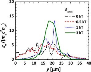
Figure 3. Perpendicular distribution of beam energy density observed at x = 37 µm and t = 1.05 ps.
Download figure:
Standard image High-resolution image3. Converging field effects
In FIREX experiments, we use cone-attached spherical shell targets. To apply kilotesla-class magnetic fields, a capacitor-coil target is installed on the fusion target. Basically B fields are applied before the fuel implosion, since the timescale of B-field generation and its penetration (or diffusion) into conductive plasmas is comparable to the implosion timescale. The pre-applied magnetic fields are compressed by the fuel shell implosion, and then the field structure becomes a converging mirror one; the fields are weak around the fast-electron generation point, that is the low-density relativistic laser–plasma interaction region, and then it is intensified towards the dense core region. In such a converging structure, we are concerned about the reflection of fast electrons due to mirror fields. To evaluate the mirror effects, we assumed the converging fields as the initial B-field structure in PIC simulations, where the target and the laser parameters are the same as before. To set the initial profile of the converging B field, four linear currents flowing in the z direction were assumed and the B-field profile was calculated using the Biot–Savart law. Then,
 is satisfied for all cases. In figure 4, an example of initial B-field structure is shown. In this case, the positions (x [µm], y [µm]) of the four currents are (61.4, 15), (61.4, −15), (−22.6, 15) and (−22.6, −5) and the absolute value of current is 4 × 10⁵ A. A part of the calculated B-field profile was used as the initial B-field profile in PIC simulations. By varying the positions and strengths of the four currents, we change the mirror ratio, defined as the ratio of the B-field strength on the x = 8 µm line (the initial laser critical density line) to that on the x = 37 µm line (fast-electron observation line). In the case of figure 4, the mirror ratio along the central laser axis RM,c is Bc,o/Bc,i = 3.93, and the mirror ratio RM,10µm along the B-field line passing through the point 10 µm away from the central laser axis in the y direction on the critical density line (corresponding to the beam edge region in figure 2) is B10μm,o/B10µm,i = 4.4. In the following discussion, we use RM,10µm as the mirror ratio. We carried out the 2D PIC simulations under converging fields with a mirror ratio of RM,10µm = 4.4−19.5.
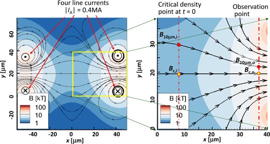
Figure 4. An example of the initial converging B-field profile. Left, positions and directions of the four linear currents flowing in the z direction. The B-field profile formed by four currents was calculated using the Biot–Savart law. Right, part of the B-field profile used as the initial profile in a PIC simulation. The mirror ratio RM,c is defined as Bc,o/Bc,i, and RM,10µm is defined as B10µm,o/B10µm,i.
Download figure:
Standard image High-resolution imageIn figure 5, the spatial profiles of fast-electron energy density and magnetic field structure are shown for RM,10µm = 4.4. In this case, some of the fast electrons are scattered or reflected due to the mirror fields. However, it is found that the beam can be focused around the beam axis along the magnetic field lines. Magnetic-pipe-like structure is also observed. Compared with the uniform 3 kT field case (figure 2(e)), the beam energy density around the beam axis at x = 37 µm becomes higher (figure 5(e)), which means that the beam focusing is more effective in the moderate-converging-field case.

Figure 5. Spatial profiles at 990 fs for RM,10µm = 4.4. (a), (b) 2D profiles of (a) fast-electron energy density εe normalized by mec2ncr, where me and c are the electron rest mass and the speed of light and (b)
 (kT) and (c)–(e) 1D perpendicular profiles of (c) Bx, (d) Bz and (e) normalized εe observed at x = 37 µm.
Download figure:
Standard image High-resolution imageIn figure 6 we compare the perpendicular distribution of the time-integrated beam energy per unit area passing through x = 37 µm among the no-external field case, the uniform 3 kT field case and the converging field cases. Compared with the uniform 3 kT case, the peak value of beam energy is intensified and the width of distribution becomes smaller for the converging mirror field cases. We evaluated the energy conversion efficiency ηL → fe,4µm of the heating laser to the beam energy of forward-directed fast electrons observed at x = 37 µm (about 20 µm propagation from the interaction region) within y = 17−21 µm (4 µm width). In FIREX experiments, the imploded core size is smaller than that of the laser spot. We hence set an observation width narrower than the laser spot size (6 µm FWHM) in the present simulations. The energy coupling ηL → fe,4µm is plotted as a function of mirror ratio RM,10µm in figure 7. The value of ηL → fe,4µm is twice as large for the uniform 3 kT field case compared with the case without external fields. For the moderately converging field cases (RM,10µm = 4.4 and 8.2), further enhancements are observed; it increases about threefold. However, for RM,10µm = 19.5, though the peak value of beam energy in figure 6 is higher than that for the uniform 3 kT case, ηL → fe,4µm becomes smaller than that for the uniform 3 kT case and close to the value for the case without external field. The results indicate that the moderately converging field (RM,10µm ≲ 10) can effectively guide and focus the fast-electron beam generated by picosecond order relativistic laser–plasma interaction. For RM,10µm > 20, however, the mirror reflection effect exceeds the guiding effect.
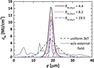
Figure 6. Comparison of perpendicular distributions of time-integrated beam energy passing through x = 37 µm per unit area, εfe, among no-external-field case, uniform 3 kT case and converging field cases.
Download figure:
Standard image High-resolution image
Figure 7. Energy conversion efficiency of the heating laser to the forward-directed fast electrons observed at x = 37 µm within y = 17 − 21 µm (4 µm width) as a function of mirror ratio RM,10µm. The value for the case without external field is shown by a broken line.
Download figure:
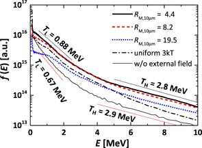
Standard image High-resolution imageWe also evaluated the energy spectra of the forward-directed fast-electron beam (E > 100 keV) by counting the forward-directed fast electrons passing though the x = 37 µm line within 4 µm width (17.4 µm < y < 21.4 µm) from t = 0 to the end of the simulation, and show them in figure 8. In all cases, the spectrum can be fitted by a sum of two exponential profiles, i.e. f(E) ∝ AL exp(−E/TL) + AH exp(−E/TH). The low-energy component (E ≲ 2 MeV) has temperature lower than 1 MeV, and the higher one (E ≳ 5 MeV) has temperature ∼3 MeV. Such a two-temperature profile is typically observed for the case of existing pre-plasmas. Compared to the no-external-field case, the number of the fast electrons is increased in the whole energy region for the cases of uniform 3 kT field and of converging field with RM,10µm = 4.4. With increasing mirror ratio from RM,10µm = 4.4, the fast-electron number starts to decrease, and the reduction is pronounced in the low-energy region (E ⩽ 1 MeV). These low-energy fast electrons mainly contribute to the core heating. Thus, the reduction of core heating efficiency is a concern even if beam energy is higher than that for the case without external field. From these simulation results, for guiding and focusing the diverging beam, the mirror ratio should be smaller than 20 at least for the pulse condition assumed here (IL = 3 × 10¹⁹ W cm−2 and τL = 1 ps), and then the control of the magnetic field structure at the heating pulse injection timing is indispensable.
Figure 8. Comparison of time-integrated energy spectrum of forward-directed fast-electron beam (E > 100 keV) observed at x = 37 µm within 4 µm width (17.4 µm < y < 21.4 µm) among no-external-field case, uniform 3 kT case and converging field cases.
Download figure:
Standard image High-resolution image
In the previous review paper [16], beam guiding by a magnetic pipe was discussed for the ignition-scale electron beam (beam energy Eb > 100 kJ, intensity Ib ∼ 1020 − 1021 W cm−2, pulse duration τb ∼ 20 ps). It was reported that, in the case of such high-energy beams, the direction of the longitudinal B field affects the guiding performance. Though we have performed the simulations by changing the signs of Bx and By for external fields to check the dependence of the guiding effect on the direction of the B field, there was no difference in the guiding performance. This is due to the lower intensity and shorter pulse duration of electron beams compared with the previous work. Our beam parameters (Eb ≲ 1 kJ, Ib ∼ 1019 W cm−2, τb ∼ 1 ps) are much lower than those for the ignition-scale study. In the previous study, the difference can be observed in the later phase (t > 2 ps), but before this (t < 2 ps) the difference is negligible. (See figure 27, right, of [16].) Our simulation region corresponds to the early phase of beam injection in ignition-scale simulation, so the difference in beam propagation due to the direction of B fields was not observed in our simulations.
4. Concluding remarks
Beam guiding by external fields for FIREX-class experiments was investigated by 2D collisional PIC simulations. It was demonstrated that a fast-electron beam with a large divergence angle generated by a relativistic laser–plasma interaction with the laser intensity of 3 × 10¹⁹ W cm−2 and the duration of 1 ps can be successfully focused by moderately converging fields (RM,10µm ≲ 10). In addition, the formation of magnetic-pipe-like structure due to the resistive effects was shown, which cannot be observed in the collisionless simulations. The formation of magnetic-pipe-like structure indicates a possibility of beam guiding under the higher mirror fields which may be formed in the ignition-scale or high-gain target implosion. However, when the mirror ratio is extremely high, e.g. RM > 100, most of the fast electrons are reflected before reaching such a high-mirror-ratio region, and then the formation of magnetic-pipe-like structure cannot be expected. In the implosion simulation [27] for a cone-attached CD shell target with B field externally applied by a one-turn coil, the ratio of B-field strength at the cone tip to that in the region between the cone tip and the dense core reaches more than 100 at maximum compression. In such a case, the fast electrons could not penetrate the very high-RM region, and then they never reach the dense core. Thus, to enhance the heating efficiency by external B field, the optimization of applied timing and initial configuration of external B field to form the moderate-RMB-field structure at the maximum compression is necessary. Further investigation of the beam guiding and enhancing the heating efficiency is needed, such as the laser intensity dependence, pulse duration dependence and guiding under higher mirror fields including the core heating process. Moreover, experimental demonstration is indispensable.
Acknowledgments
This work is partially conducted under the joint research projects of the Institute of Laser Engineering, Osaka University (FIREX project), and with the support of the NIFS Collaboration Research program (NIFS12KUGK057 and NIFS14KNSS054) and JSPS KAKENHI grant number 25400534.